Device for manufacturing glass plate and method for manufacturing glass plate

A technology of a manufacturing device and a manufacturing method, which is applied in the field of glass plate manufacturing devices, can solve problems such as the thickness of the glass plate, and achieve the effects of increasing the area, improving productivity and yield.

Active Publication Date: 2015-12-23
ASAHI GLASS CO LTD
View PDF7 Cites 0 Cited by
  • Summary
  • Abstract
  • Description
  • Claims
  • Application Information

AI Technical Summary

Problems solved by technology

If the shrinkage is too large, the thickness of the finis

Method used


Image

  • Device for manufacturing glass plate and method for manufacturing glass plate
  • Device for manufacturing glass plate and method for manufacturing glass plate
  • Device for manufacturing glass plate and method for manufacturing glass plate

Examples


Example Embodiment

[0033] Hereinafter, an embodiment of the present invention will be described with reference to the drawings. In the following drawings, the same or corresponding structures are denoted by the same or corresponding symbols, and the description thereof is omitted.

[0034] [Embodiment 1]
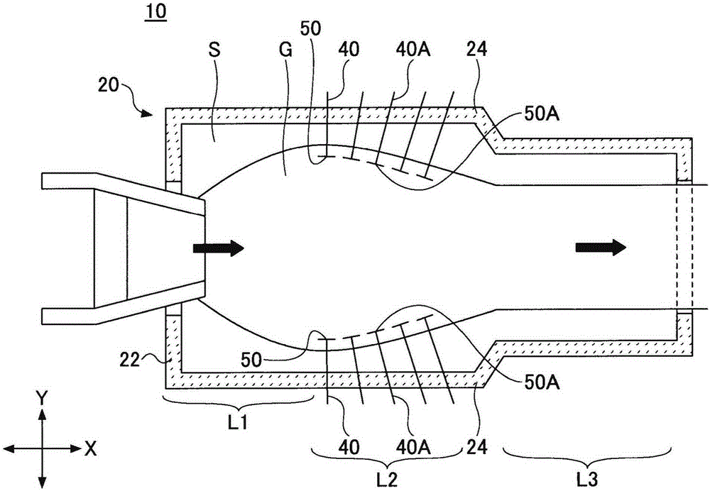
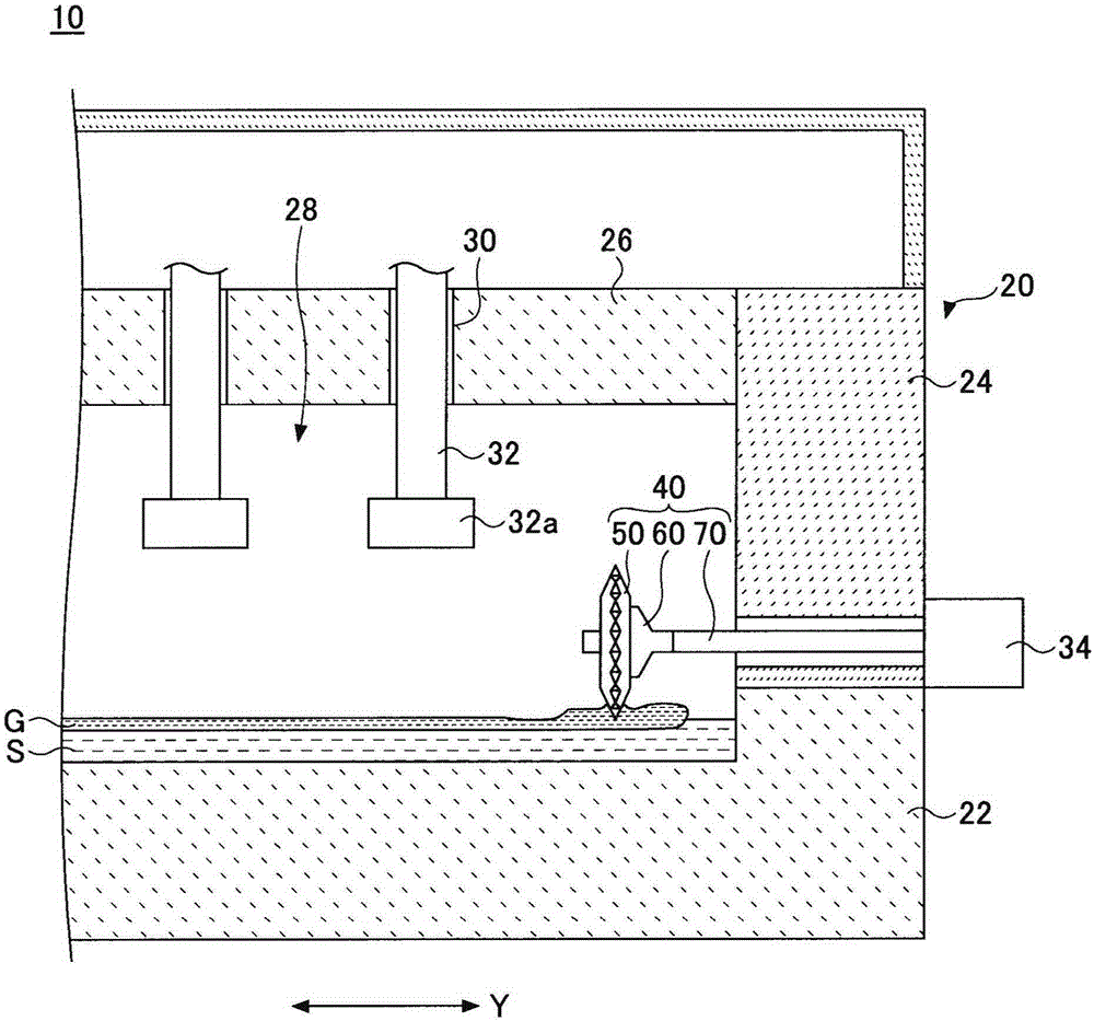
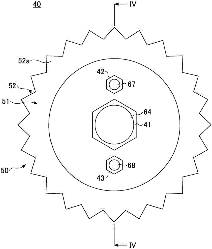
[0035] figure 1 It is a transverse cross-sectional view of an example of a schematic configuration of the manufacturing apparatus 10 of the glass plate according to Embodiment 1 as viewed from above. As mentioned later, the manufacturing apparatus 10 of the glass plate of this embodiment has the some support roll 40 and the support roll 40A made from ceramics. figure 2 It is a partial longitudinal cross-sectional view which shows an example of the attachment structure of the backup roll 40 of the manufacturing apparatus of the glass plate of Embodiment 1. Figure 5 It is a partial longitudinal cross-sectional view which shows an example of the attachment structure of 40 A of ceramic backu...


PUM


Abstract

In this device for manufacturing a glass plate, ceramic support rollers (40A) are provided to the inflow side of a glass ribbon (G) and metal support rollers (40) are provided to the downstream side of the flow direction of the glass ribbon (G) in a glass roller arrangement row (1). The ceramic support rollers (40A-1) and (40A-2) that are arranged downstream from the support rollers (40-1) and (40-2) are arranged so that the roller marks (100) and (110) of ceramic rotating members (50A-1) and (50A-2) overlap with the roller mark depressions (102) and (112) of the support rollers (40-1) and (40-2) that are arranged on the upstream side.

Description

technical field [0001] This invention relates to the manufacturing apparatus of a glass plate, and the manufacturing method of a glass plate. Background technique [0002] As a forming method of a glass plate, the float method is widely used. The float method is a method in which molten glass is introduced onto molten metal (for example, molten tin) accommodated in a bath, the molten glass is made to flow in a predetermined direction, and a ribbon-shaped glass ribbon is produced. After the glass ribbon is slowly cooled while flowing in the horizontal direction, it is lifted from the molten metal by lifting rollers and annealed in an annealing furnace to form sheet glass. After the plate glass is carried out from the annealing furnace, it is cut into a predetermined size and shape by a cutting machine to produce a finished glass plate. [0003] However, glass that is thinner than the equilibrium thickness tends to shrink in the width direction. If the shrinkage is too larg...

Claims


Application Information

Patent Timeline
IPC IPC(8): C03B18/06
CPCC03B18/06Y02P40/57
Inventor 郡司海伴信之
Owner ASAHI GLASS CO LTD
Why Eureka
Try Eureka