Burner assembly and method for combustion of gaseous or liquid fuel

A technology for burning gas and liquid fuel, which is applied in gas fuel burners, combustion methods, burners, etc., and can solve problems such as thermal damage to the combustion chamber wall and high NOx emissions.

Active Publication Date: 2016-04-27
METSO OUTOTEC (FINLAND) OY
View PDF7 Cites 0 Cited by
  • Summary
  • Abstract
  • Description
  • Claims
  • Application Information

AI Technical Summary

Problems solved by technology

This hot flame with a typical maximum theoretical temperature of about 2000°C leads to very high NOx emissions and also to thermal damage to the combustion chamber walls

Method used


Image

  • Burner assembly and method for combustion of gaseous or liquid fuel
  • Burner assembly and method for combustion of gaseous or liquid fuel
  • Burner assembly and method for combustion of gaseous or liquid fuel

Examples


Embodiment Construction

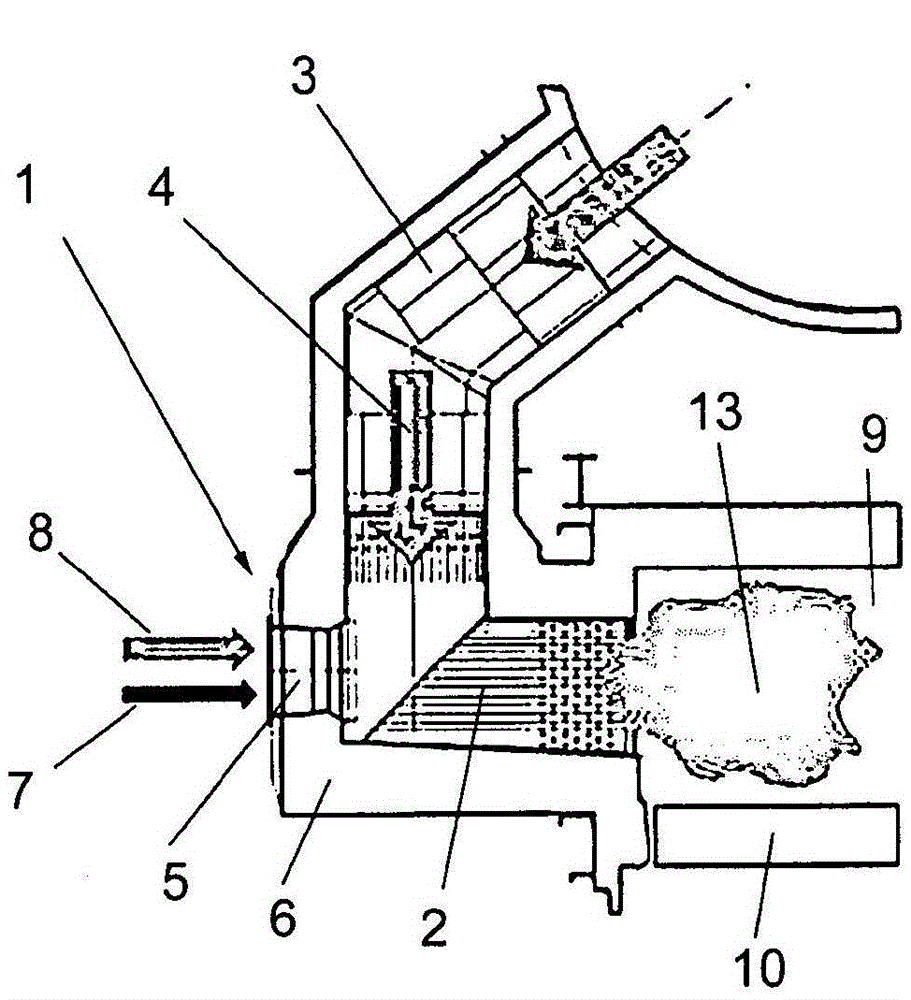
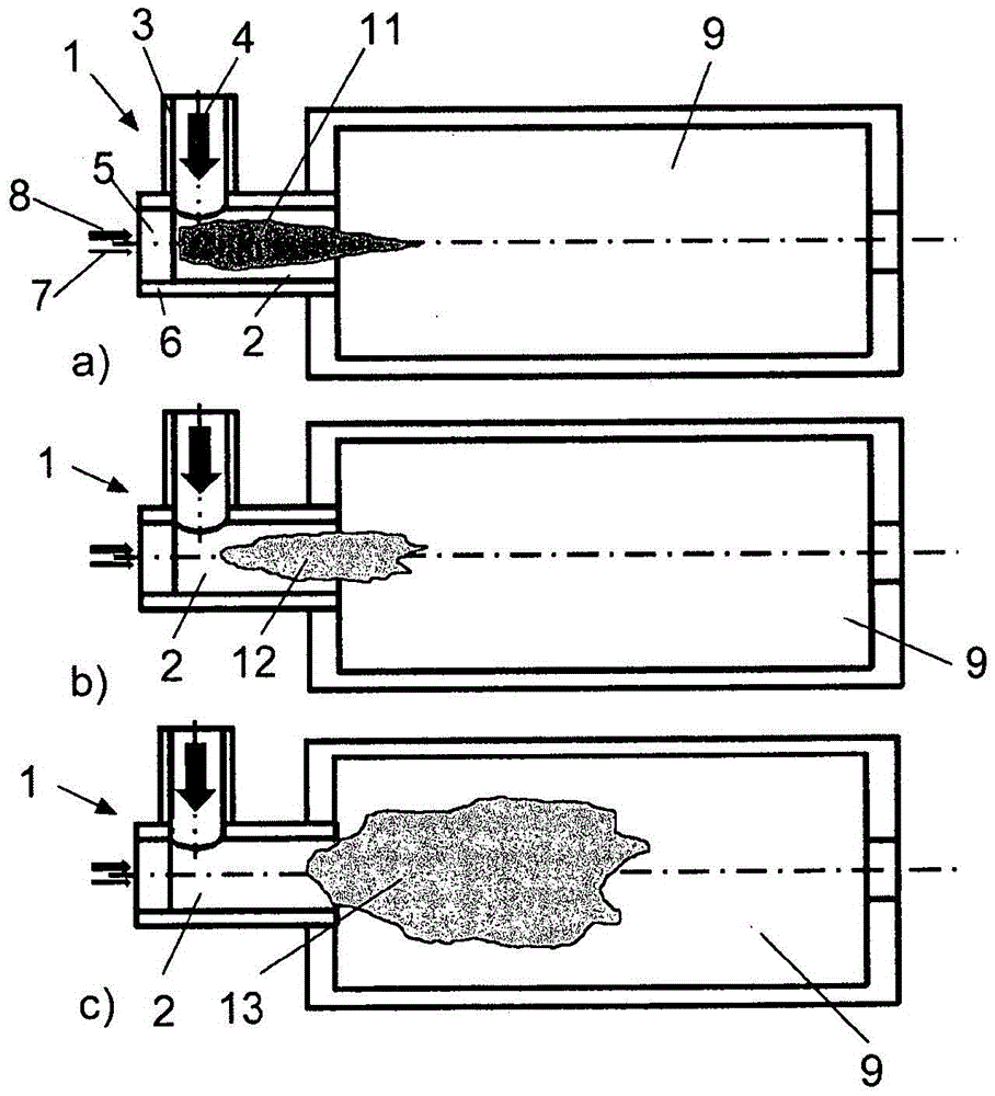
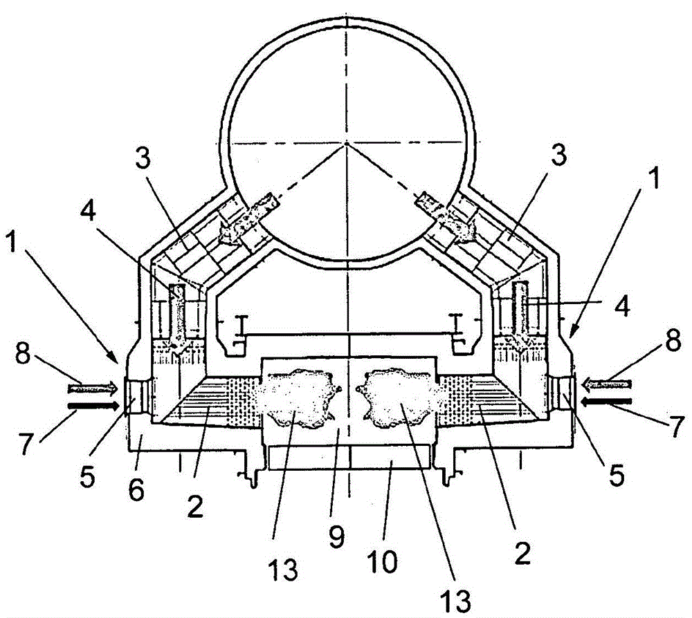
[0051] exist figure 1 In , a burner assembly 1 according to a preferred embodiment of the present invention is shown in cross-section. The burner assembly 1 has a combustion chamber 2, a main combustion air inlet 3 for feeding preheated combustion air 4 into the combustion chamber 2, and a burner 5 located in a wall 6 of the combustion chamber 2 so that through the main combustion The combustion air 4 which flows into the combustion chamber 2 through the air inlet 3 passes through the burner 5 . The burner 5 has at least one fuel supply pipe 7 and at least one air supply pipe 8 for respectively supplying fuel and primary air into the combustion chamber 2 . Furthermore, the burner 1 has a control unit or control device (not shown) for controlling the supply of fuel and primary air into the combustion chamber.

[0052] The combustion chamber 2 leads to an industrial furnace 9 where the desired treatment of the material takes place.

[0053] According to a preferred embodiment...


PUM


Abstract

Burner assembly and method for combustion of gaseous of liquid fuel The invention relates to a burner assembly (1) and a method for combustion of gaseous or liquid fuel to heat an industrial furnace (9) having a combustion chamber (2), at least one main combustion air inlet (3) for the supply of preheat- ed combustion air (4) into the combustion chamber (2), a burner (5) with at least one fuel feed (7) and at least one air feed (8) for supply of fuel and primary air into a the combustion chamber (2), wherein the burner (5) is positioned adjacent to a combustion zone of the combustion chamber (2) such that the combustion air (4) flowing into the combustion chamber (2) through the main combustion air inlet (3) is passing the burner (5) in the combustion zone and is then deflected such that the flow of preheated combustion air and the smaller flows of fuel and primary air are flowing mainly in parallel from the burner (5) to the furnace (9), and a control unit for controlling the supply of fuel and maybe primary air into the combustion chamber (2). The control unit is adapted to supply the fuel and / or the primary air from the fuel and / or air feed (7, 8) into the combustion chamber (2) with an exit velocity higher than 150 m / s.

Description

technical field [0001] The present invention relates to burner assemblies and methods for burning gaseous or liquid fuels, such as gas or oil, to heat industrial furnaces, particularly roaster furnaces, which are commonly used in moving grate pellet production plants. The burner assembly has a combustion chamber, at least one main combustion air inlet for supplying preheated combustion air into the combustion chamber, and a burner (also referred to as a burner brick) having a at least one fuel supply duct and at least one air supply duct into the combustion chamber, wherein the burner is positioned adjacent to the combustion zone of the combustion chamber such that combustion air flowing into the combustion chamber via the main combustion air inlet passes the burner in the combustion zone, and It is then diverted (for example, at the combustion chamber wall) so that the (especially larger) preheated combustion air flow and (especially smaller than the larger preheated combusti...

Claims


Application Information

Patent Timeline
Patent Type & Authority Applications(China)
IPC IPC(8): F23D14/84F23D14/22F23D99/00F23C9/00F23C7/06C22B1/24F27B21/06
CPCF23C7/06F23C9/00F23D14/22F23D14/84F23C2900/99001F23D91/02F27D99/0033Y02E20/34F23N1/02F23N3/00
Inventor A·穆恩科H·科勒
Owner METSO OUTOTEC (FINLAND) OY
Why Eureka
Try Eureka