Combustor assembly and method for burning gaseous or liquid fuels

一种燃烧气体、燃烧器的技术,应用在气体燃料燃烧器、燃烧方法、燃烧器等方向,能够解决燃烧室壁热损害、高NOx排放等问题

Active Publication Date: 2018-04-06
METSO OUTOTEC (FINLAND) OY
View PDF7 Cites 0 Cited by
  • Summary
  • Abstract
  • Description
  • Claims
  • Application Information

AI Technical Summary

Problems solved by technology

This hot flame with a typical maximum theoretical temperature of about 2000°C leads to very high NOx emissions and also to thermal damage to the combustion chamber walls

Method used


Image

  • Combustor assembly and method for burning gaseous or liquid fuels
  • Combustor assembly and method for burning gaseous or liquid fuels
  • Combustor assembly and method for burning gaseous or liquid fuels

Examples


Embodiment Construction

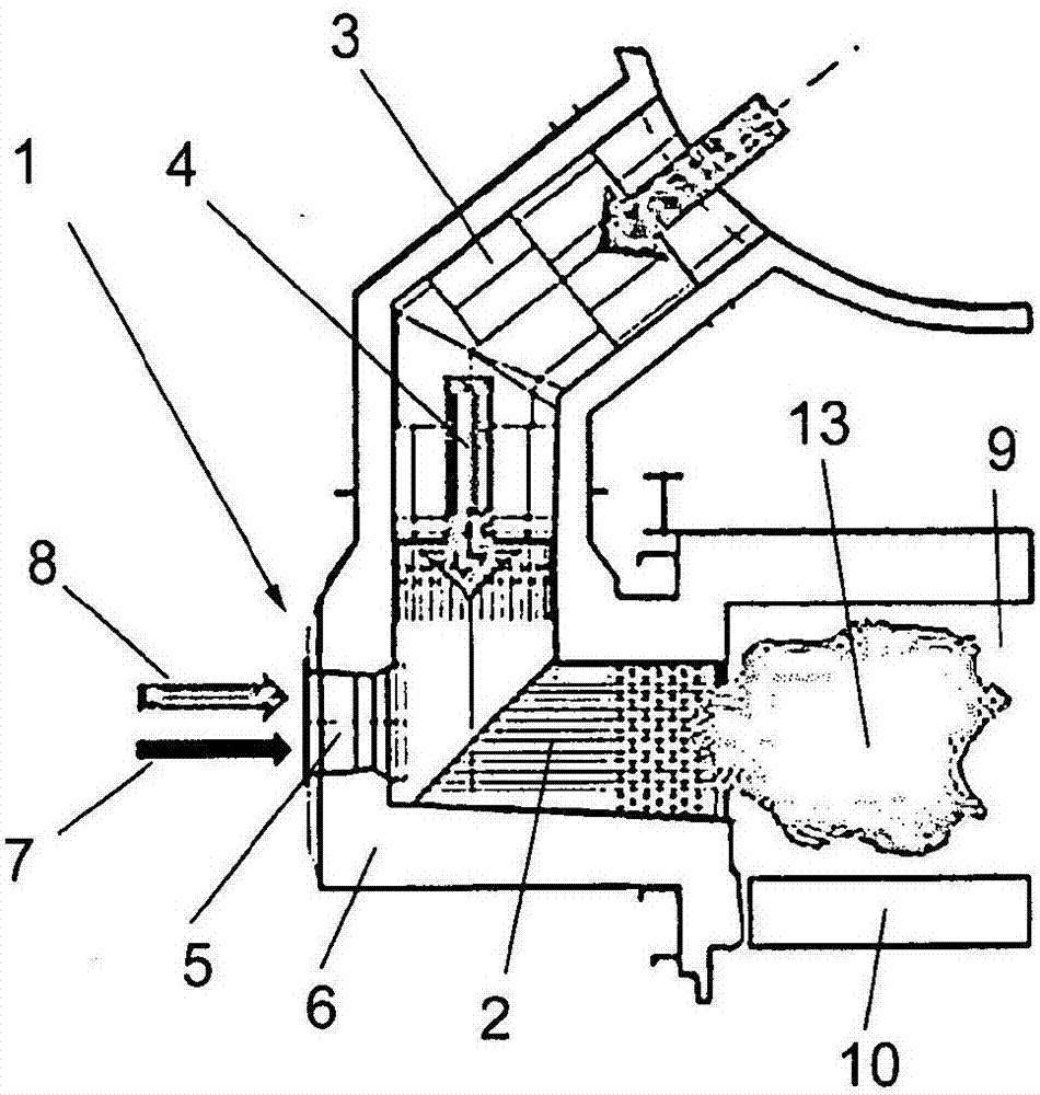
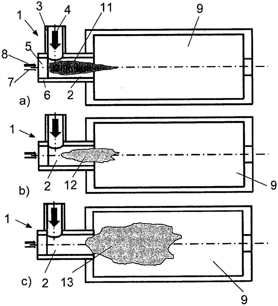
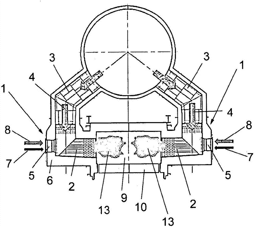
[0051] exist figure 1 In , a burner assembly 1 according to a preferred embodiment of the present invention is shown in cross-section. The burner assembly 1 has a combustion chamber 2, a main combustion air inlet 3 for feeding preheated combustion air 4 into the combustion chamber 2, and a burner 5 located in a wall 6 of the combustion chamber 2 so that through the main combustion The combustion air 4 which flows into the combustion chamber 2 through the air inlet 3 passes through the burner 5 . The burner 5 has at least one fuel supply pipe 7 and at least one air supply pipe 8 for respectively supplying fuel and primary air into the combustion chamber 2 . Furthermore, the burner 1 has a control unit or control device (not shown) for controlling the supply of fuel and primary air into the combustion chamber.

[0052] The combustion chamber 2 leads to an industrial furnace 9 where the desired treatment of the material takes place.

[0053] According to a preferred embodiment...


PUM

PropertyMeasurementUnit
temperatureaaaaaaaaaa

Abstract

Combustor assemblies and methods for burning gaseous or liquid fuels. The present invention relates to a burner assembly (1) and method for heating an industrial furnace (9) by burning a gaseous or liquid fuel, the burner assembly having: a combustion chamber (2); at least one main combustion air inlet (3) with For supplying preheated combustion air (4) into the combustion chamber (2); the burner (5) has at least one fuel supply pipe (7) and at least one air supply pipe (8) for respectively supplying fuel and primary Air is fed into the combustion chamber (2), wherein the burner (5) is positioned near the combustion zone of the combustion chamber (2) so that the combustion air (4) flowing into the combustion chamber (2) through the main combustion air inlet (3) ) passes the burner (5) in the combustion zone and then turns so that the preheated combustion air flow and the smaller fuel flow flow from the burner (5) to the industrial furnace (9) substantially parallel to the primary air flow; and control A unit for controlling the supply of fuel and possibly primary air into the combustion chamber (2). The control unit is adapted to feed fuel and / or primary air from the fuel supply pipe and / or the air supply pipe (7, 8) into the combustion chamber (2) at an outlet velocity higher than 150 m / s.

Description

technical field [0001] The present invention relates to burner assemblies and methods for burning gaseous or liquid fuels, such as gas or oil, to heat industrial furnaces, particularly roaster furnaces, which are commonly used in moving grate pellet production plants. The burner assembly has a combustion chamber, at least one main combustion air inlet for supplying preheated combustion air into the combustion chamber, and a burner (also referred to as a burner brick) having a at least one fuel supply duct and at least one air supply duct into the combustion chamber, wherein the burner is positioned adjacent to the combustion zone of the combustion chamber such that combustion air flowing into the combustion chamber via the main combustion air inlet passes the burner in the combustion zone, and It is then diverted (for example, at the combustion chamber wall) so that the (especially larger) preheated combustion air flow and (especially smaller than the larger preheated combusti...

Claims


Application Information

Patent Timeline
Patent Type & Authority Patents(China)
IPC IPC(8): F23D14/84F23D14/22F23D99/00F23C9/00F23C7/06C22B1/24F27B21/06
CPCF23C7/06F23C9/00F23D14/22F23D14/84F23C2900/99001F23D91/02F27D99/0033Y02E20/34F23N1/02F23N3/00
Inventor A·穆恩科H·科勒
Owner METSO OUTOTEC (FINLAND) OY
Why Eureka
Try Eureka