Clamping ring of roll chock and its installation method

A roll bearing and installation method technology, applied in the direction of metal rolling mill stand, metal rolling, metal rolling, etc., can solve the problems of reducing the service life of spare parts, unable to shift rolls, affecting the production of rolling mills, etc. The effect of production cost and easy inspection

Active Publication Date: 2018-09-18
MAANSHAN IRON & STEEL CO LTD
View PDF6 Cites 0 Cited by
  • Summary
  • Abstract
  • Description
  • Claims
  • Application Information

AI Technical Summary

Problems solved by technology

[0003] One is the impact and axial force on the clamping ring of the roll bearing seat during the production process of the rolling mill, which will cause the locking bolt of the clamping ring to fail, and cause the clamping ring to clamp and fix the bearing seat. Roll shifting was impossible during the process, and the bearing seat was stuck in the rolling mill stand, which seriously affected the production of the rolling mill and caused a large roll changing accident in the rolling mill
[0004] Second, it is difficult to find the failure and fall-off of the clamping ring of the roll bearing seat. The working conditions of the clamping ring of each bearing seat are different, and the period of failure of the locking bolt of the clamping ring is also different, which brings more problems to spot inspection and replacement of the clamping ring. Difficult, 3-4 clamping ring failures and shedding incidents occur every year, and the impact of clamping ring detachment on the rolling mill cannot be avoided
At present, we can only strengthen the frequency of spot inspection of the bearing seat, shorten the replacement cycle of the clamping ring, reduce the service life of spare parts, and increase the production cost

Method used


Image

  • Clamping ring of roll chock and its installation method

Examples


Embodiment Construction

[0019] The specific implementation manner of the present invention will be described in further detail below by describing the best embodiment with reference to the accompanying drawings.

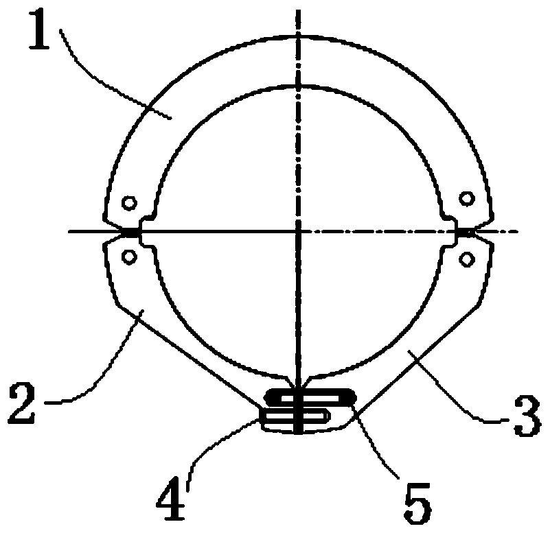
[0020] Such as figure 1 As shown, the clamping ring of the roll bearing seat includes the clamping ring I1, one end of the clamping ring I1 is connected with the clamping ring II2, the other end of the clamping ring I1 is connected with the clamping ring III3, and the end of the clamping ring II2 and the end of the clamping ring III3 pass through The locking bolt 4 is connected, and the end of the snap ring II2 and the snap ring III3 connected by the locking bolt 4 is provided with a connecting plate 5 connecting the snap ring II2 and the snap ring III3; the connecting plate 5 is located above the locking bolt 4; the locking bolt 4 Realize the locking of the clasp I1, clasp II2 and clasp III3, and increase the connecting plate 5 at the same time. The connecting plate 5 has a locking functio...


PUM


Abstract

The invention discloses a roll bearing chock clamping ring which comprises a clamping ring body I. One end of the clamping ring body I is connected with a clamping ring body II, and the other end of the clamping ring body I is connected with a clamping ring body III. The end of the clamping ring body II and the end of the clamping ring body III are connected through a lock bolt. A connecting plate for connecting the clamping ring body II and the clamping ring body III is arranged at the ends, connected through the lock bolt, of the clamping ring body II and the clamping ring body III. Under the combined action of the lock bolt and the connecting plate, the clamping ring is reliably and steadily assembled on a bearing chock. The connecting plate is taken as an added fastening measure, and after the lock bolt loses efficacy, the connecting plate plays a locking function and has an anti-dropping function. More importantly, when the connecting plate deforms and breaks, a warning effect can be directly and obviously achieved, point inspection and replacement are facilitated, safety is improved, and normal production with a rolling mill is guaranteed.

Description

technical field [0001] The invention relates to a roll chock of a hot-rolled strip, in particular to a clamping ring of the roll chock and an installation method thereof. Background technique [0002] The clamping ring of the roll bearing seat is a clamping structure for the assembly and fixing of the bearing seat. In the prior art, the clamping ring of the roll chock has disadvantages. [0003] One is the impact and axial force on the clamping ring of the roll bearing seat during the production process of the rolling mill, which will cause the locking bolt of the clamping ring to fail, and cause the clamping ring to clamp and fix the bearing seat. Roll shifting was impossible during the process, and the bearing housing was stuck in the rolling mill stand, which seriously affected the production of the rolling mill and caused a major roll changing accident in the rolling mill. [0004] Second, it is difficult to find the failure and fall-off of the clamping ring of the rol...

Claims


Application Information

Patent Timeline
Patent Type & Authority Patents(China)
IPC IPC(8): B21B31/02
CPCB21B31/02
Inventor 成印明王会伟焦轩
Owner MAANSHAN IRON & STEEL CO LTD
Why Eureka
Try Eureka