Automatic spot welding device for car body board

An automatic spot welding and sheet metal technology, applied in auxiliary devices, vehicle parts, welding equipment, etc., can solve the problems of large structure, complexity of welding tooling, and difficult to guarantee the quality of appearance in batches.

Active Publication Date: 2016-05-04
MH ROBOT & AUTOMATION
View PDF6 Cites 4 Cited by
  • Summary
  • Abstract
  • Description
  • Claims
  • Application Information

AI Technical Summary

Problems solved by technology

The development of vehicle models is changing with each passing day, and the complex body parts have caused great difficulties in the clamping and positioning of the fixture and the spot welding work. During the welding process, the body-in-white needs a special clamping and positioning mechanism to clamp and position it, and then adopt welding tools of different structures For spot welding, with the increase of car models, it is necessary to set up multiple sets of clamping and positioning mechanisms on the welding platform to clamp and position the body-in-white of different models, and it is necessary to set up welding tools of different structures to provide welding torches in different directions for spot welding. Welding, so the above-mentioned welding tooling is very large and complex in structure, and the production cost is high
In addition, if manual spot welding is used, the appearance quality of the body is difficult to guarantee in batches and the production efficiency is low. Now there is an urgent need for a welding tool with a simple structure, low production cost, and batch spot welding of the body-in-white.

Method used


Image

  • Automatic spot welding device for car body board
  • Automatic spot welding device for car body board
  • Automatic spot welding device for car body board

Examples


Embodiment Construction

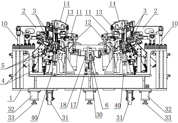
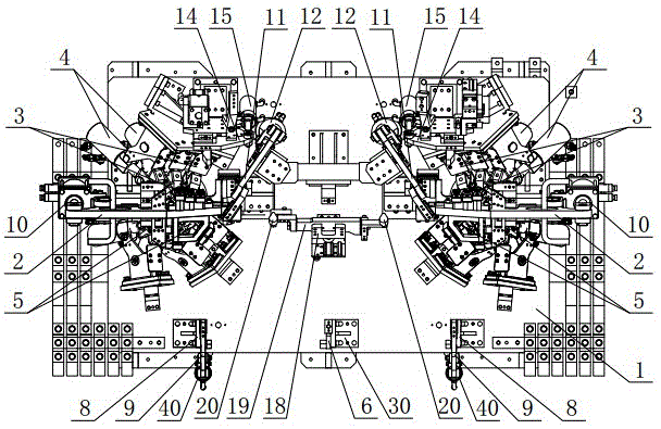
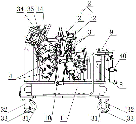
[0020] Such as figure 1 , figure 2 with image 3 As shown, the present invention provides an embodiment of an automatic spot welding device for vehicle body panels. This embodiment is used for spot welding of car door panels. It includes a support frame 1, and the bottom of the support frame 1 is equipped with walking wheels 31. The bottom of support frame 1 is also equipped with the parking cylinder 32 that piston rod is arranged downwards, and the downward extension end of the piston rod of parking cylinder 32 is equipped with parking seat 33, and the front portion of support frame 1 is equipped with plate front end positioning mechanism and The clamping mechanism at the front part of the plate, the rear part of the support frame 1 is equipped with a side positioning rear clamping mechanism which is oppositely arranged and respectively carries out width positioning on both sides of the plate, that is to say, the side positioning rear clamping mechanism can The two sides o...


PUM


Abstract

The invention discloses an automatic spot welding device for a car body board, comprising a support frame, wherein a board front end positioning mechanism and a board front part clamping mechanism are arranged at the front part of the support frame, lateral positioning and rear clamping mechanisms which are oppositely arranged and are respectively used for carrying out width positioning on two lateral parts of the board are arranged at the rear part of the support frame, upper electrode stands driven to swing up and down by an upper electrode power mechanism are arranged on the support frame, a plurality of upper electrodes connected with a main welding machine are respectively arranged on the upper electrode stands, a plurality of lower electrode driving cylinders which are located below the upper electrodes and are arranged corresponding to the upper electrodes in position are arranged on the support frame, lower electrodes which are connected with the main welding machine and matched with the upper electrodes to carry out spot welding are arranged on the lower electrode driving cylinders, and a middle positioning and tightening mechanism which can prop against a board is arranged in the middle of the support frame. According to the invention, the car body board can be clamped, automatic spot welding can be carried out on the car body board, and the device has the advantages of being high in spot welding quality and improving the appearances of large-batch car bodies.

Description

technical field [0001] The invention relates to an automatic spot welding device for body panels. Background technique [0002] The application of welding tooling is directly related to the efficiency, precision and quality of the welding process. The development of vehicle models is changing with each passing day, and the complex body parts have caused great difficulties in the clamping and positioning of the fixture and the spot welding work. During the welding process, the body-in-white needs a special clamping and positioning mechanism to clamp and position it, and then adopt welding tools of different structures For spot welding, with the increase of car models, it is necessary to set up multiple sets of clamping and positioning mechanisms on the welding platform to clamp and position the body-in-white of different models, and it is necessary to set up welding tools of different structures to provide welding torches in different directions for spot welding. Welding, so...

Claims


Application Information

Patent Timeline
Patent Type & Authority Applications(China)
IPC IPC(8): B23K37/04B23K37/00
CPCB23K37/00B23K37/0443B23K2101/006
Inventor 沈君亮兰春立毕海廷王银河孙希趵
Owner MH ROBOT & AUTOMATION
Why Eureka
Try Eureka