Device for clamping and releasing workpiece

A workpiece clamp and workpiece technology, applied in the field of workpiece clamping and loosening devices, can solve problems such as poor stamping accuracy, large workload, and difficulty in controlling accuracy, and achieve precise positioning, improved machining accuracy, great practical value and creativity. Effect

Inactive Publication Date: 2016-05-04
JIANGSU HONGBAO HARDWARE
View PDF5 Cites 1 Cited by
  • Summary
  • Abstract
  • Description
  • Claims
  • Application Information

AI Technical Summary

Problems solved by technology

[0002] In the process of traditional metal tool processing, due to the irregular shape of the workpiece to be processed, it is not easy to control the accuracy during drilling and other operations, so repeated clamping is required, and the processing accuracy of the workpiece is repeatedly required to be tested, and the workload is very large. , a lot of defective products
[0003] For example, during the manufacturing process of metal tool pliers, the center hole needs to be punched or twisted, and the center hole of the tool pliers is not set on a plane. The traditional process uses a tooling fixture to fix the two ends of the tool pliers for drilling, but tool pliers are often prone to accidents. Offset in various directions, resulting in poor stamping accuracy
It is also used to place a soft material pad on the plane where the workpiece is placed on the fixture to determine the position of the workpiece. The effect is better than the former, but it still lacks efficiency and accuracy.

Method used


Image

  • Device for clamping and releasing workpiece
  • Device for clamping and releasing workpiece

Examples


Embodiment 1

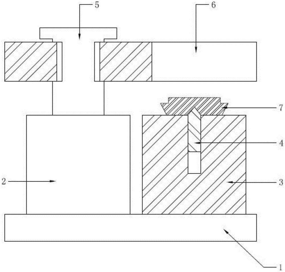
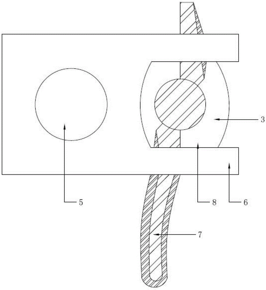
[0023] A device for clamping and loosening workpieces, comprising a base 1, the base 1 is provided with a driving mechanism 2 and a positioning seat 3, the top of the driving mechanism 2 is connected to a pressing block 6 through a transmission mechanism 5, and the pressing block 6 One end extends to the top of the entire positioning seat 3, and an open working window 8 is provided in the middle of the end of the pressure block 6 to face the center position of the positioning seat 3, and the center position of the upper end surface of the positioning seat 3 is provided with a downwardly fixed positioning pin 4. The positioning pin 4 can move in the vertical direction inside the positioning seat 3, and the positioning pin 4 is installed and fixed to the workpiece 7 to be worked.

[0024] The driving mechanism 2 is arranged on one side of the base 1 , and the positioning seat 3 is arranged on the other side of the base 1 . The flexible connection between the bottom end of the po...

Embodiment 2

[0027] The difference from Embodiment 1 is that there are two driving mechanisms 2, which are respectively arranged on both sides of the base 1. The seat 3 is located in the middle of the base 1 .

Embodiment 3

[0029] The difference from Embodiment 1 is that no movable mechanism is provided at the bottom of the positioning pin 4, and the body of the positioning pin 4 is a sliding device.


PUM


Abstract

The invention relates to the field of metal tool manufacturing, and provides a device for clamping and releasing a workpiece. The device comprises a base, and is characterized in that the base is provided with a drive mechanism and a positioning base, the drive mechanism is connected with a pressing block through a transmission mechanism, an opened working window is formed in the pressing block and is right opposite to the positioning base, and a positioning pin is arranged at the center of the upper end face of the positioning base. Different from a traditional positioning mode depending on positioning of the appearance or side face of the workpiece, the structural design of the independent positioning pin is adopted, positioning references of some processes can be unified, machining precision can be greatly improved, and then the process of clamping the workpiece at a time and machining the workpiece multiple times is achieved.

Description

technical field [0001] The invention relates to the field of metal tool manufacturing, in particular to a device for clamping and releasing workpieces. Background technique [0002] In the process of traditional metal tool processing, due to the irregular shape of the workpiece to be processed, it is not easy to control the accuracy during drilling and other operations, so repeated clamping is required, and the processing accuracy of the workpiece is repeatedly required to be tested, and the workload is very large. , there are a lot of defective products. [0003] For example, in the manufacturing process of metal tool pliers, the center hole needs to be punched or twisted, and the center hole of the tool pliers is not set on a plane. The traditional process uses a tooling fixture to fix the two ends of the tool pliers to implement drilling, but tool pliers are often prone to accidents. Various directions are offset, resulting in poor stamping accuracy. There is also a met...

Claims


Application Information

Patent Timeline
Patent Type & Authority Applications(China)
IPC IPC(8): B23Q3/06B23Q3/08
CPCB23Q3/06B23Q3/08B23Q3/082
Inventor 秦卫华吕旗东朱剑峰
Owner JIANGSU HONGBAO HARDWARE
Why Eureka
Try Eureka