Laser material increasing and decreasing combined manufacturing method and device

A technology of subtractive manufacturing and adding and subtracting materials, which is applied in the field of 3D printing, can solve problems such as processing limitations and compatibility issues, and achieve good compatibility, simple control, and improved forming accuracy.

Inactive Publication Date: 2016-05-04
CHONGQING INST OF GREEN & INTELLIGENT TECH CHINESE ACADEMY OF SCI
View PDF4 Cites 60 Cited by
  • Summary
  • Abstract
  • Description
  • Claims
  • Application Information

AI Technical Summary

Problems solved by technology

However, since CNC is a mechanical processing technology, there are problems in compatibility with technologies such as LENS and SLM, which makes it difficult to overcome difficulties in the control of a

Method used


Image

  • Laser material increasing and decreasing combined manufacturing method and device
  • Laser material increasing and decreasing combined manufacturing method and device
  • Laser material increasing and decreasing combined manufacturing method and device

Examples


Embodiment 1

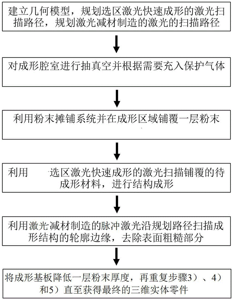
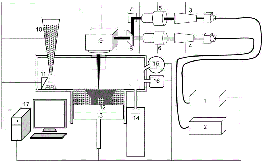
[0044] The following combination figure 1 and figure 2 , the present invention is described in detail by taking the composite manufacturing of titanium alloy based on selective laser rapid prototyping by laser addition and subtraction as an example. The selected titanium alloy powder is a nearly spherical powder with a particle size of 30-50 μm.

[0045] First, design the geometric model of the titanium alloy structure for forming, plan the scanning path of the laser for selective laser rapid prototyping, and plan the scanning path of the pulsed laser for laser subtractive manufacturing; then use the atmosphere control system to vacuumize the forming chamber and Fill the protective gas argon, and control the atmosphere during the forming process; use the powder feeder 10 to feed titanium alloy powder, and use the scraper 11 of the powder spreading system to spread a layer of titanium alloy with a thickness of 50-70 μm on the forming substrate powder; the laser beam emitted b...

Embodiment 2

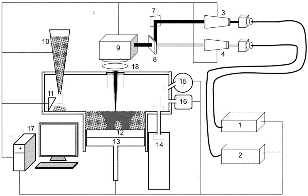
[0047] The following combination figure 1 and image 3 , with Al 2 o 3 The present invention is described in detail by taking multi-wavelength laser selective rapid prototyping of ceramics as an example. Selected Al 2 o 3 The ceramic powder is a nearly spherical powder with a particle size of 30-60 μm.

[0048] First, design the geometric model of the ceramic structure used for forming, plan the scanning path of the laser for selective laser rapid prototyping, and plan the scanning path of the pulsed laser for laser subtractive manufacturing; then, use the atmosphere control system to vacuumize the forming chamber And control the degree of vacuum in the forming cavity; Utilize powder feeder 10 to send into Al 2 o 3 Ceramic powder, using the scraper 11 of the powder spreading system to spread a layer of Al with a thickness of 50-70 μm on the forming substrate 2 o 3 Ceramic powder; the laser beam emitted by laser I1 for selective laser rapid prototyping and focused on t...


PUM


Abstract

The invention discloses a laser material increasing and decreasing combined manufacturing method and device. Specifically, the method comprises the steps that a geometric model of an entity part is established, a scanning path of a laser for quick laser forming in a selected area is planned, and a scanning path of a laser for laser material decreasing manufacturing is planned; a forming cavity is vacuumized and filled with protection gas; a layer of powder is laid in a forming area through a powder spreading system; laid materials to be formed are scanned through the laser for quick laser forming in the selected area, and structure forming is carried out; the contour edge of the formed structure is scanned by the pulse laser for laser material decreasing manufacturing along the planned path to remove coarse parts on the surface; the operation of powder spreading, quick laser forming in the selected area and laser material decreasing manufacturing is repeated until a final three-dimensional entity part is obtained. The invention further provides the laser material increasing and decreasing combined manufacturing device. By using the device and the method for manufacturing increased and decreased materials, the forming precision is improved; in addition, the laser is used for both increasing and decreasing the materials, so that better compatibility is achieved, and control is easier.

Description

technical field [0001] The invention belongs to the technical field of 3D printing, and in particular relates to a method for composite manufacturing of laser additive and subtractive materials, and also relates to a composite manufacturing device of laser additive and subtractive materials. Background technique [0002] High-precision flexible manufacturing is the goal pursued by the manufacturing industry. Therefore, the research and industrial development of additive manufacturing (or 3D printing) technology has become a hot spot today. As far as the forming accuracy of functional 3D printed structural parts is concerned, the forming accuracy of the selective laser rapid prototyping technology, especially the selective laser melting (SLM) technology can make the 3D printing technology reach the highest level. However, due to the size of the powder, the size of the laser focus spot, and the thermal deformation caused by rapid condensation during the forming process, the di...

Claims


Application Information

Patent Timeline
IPC IPC(8): B29C67/00B22F3/105C04B35/64B23K26/046B23K26/08B23K26/0622B33Y10/00B33Y30/00
CPCB22F3/105B22F2201/10B23K26/046C04B35/64B23K26/0622B23K26/08B29C67/00B33Y10/00B33Y30/00Y02P10/25
Inventor 段宣明范树迁曹洪忠王国玉
Owner CHONGQING INST OF GREEN & INTELLIGENT TECH CHINESE ACADEMY OF SCI
Why Eureka
Try Eureka