Discharging and conveying device of punching production line

A transmission device and production line technology, applied in the direction of conveyors, conveyor objects, mechanical conveyors, etc., can solve the problems of not being able to meet stamping parts transmission, increase labor intensity and risk factors of workers, and achieve elongation and increase transmission distance Effect

Active Publication Date: 2016-05-04
TIANJIN HENGXING MECHANICAL EQUIP
View PDF8 Cites 1 Cited by
  • Summary
  • Abstract
  • Description
  • Claims
  • Application Information

AI Technical Summary

Problems solved by technology

[0003] The punching machine is mainly composed of a feeding and discharging mechanism, a transmission mechanism, and a stamping mechanism. The feeding and discharging mechanism is used for feeding and returning materials. The workpiece is sent to the discharge mechanism to be sent out. However, the existing transmission mechanism is not specially set up for the discharge. It is mainly operated manually, and the punched workpiece is manually pushed and slid onto the conveyor frame, which increases the labor intensity of the workers. and risk factor
At the same time, the transmission track and the punching machine are fixed and cannot be moved. The distance between the transmission track and the punching machine is also fixed, which limits the transmission of stamping parts to a certain extent, and cannot meet the transmission of stamping parts of any size.

Method used


Image

  • Discharging and conveying device of punching production line
  • Discharging and conveying device of punching production line
  • Discharging and conveying device of punching production line

Examples


Embodiment 1

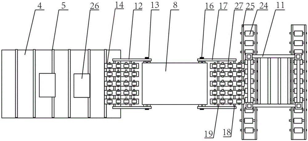
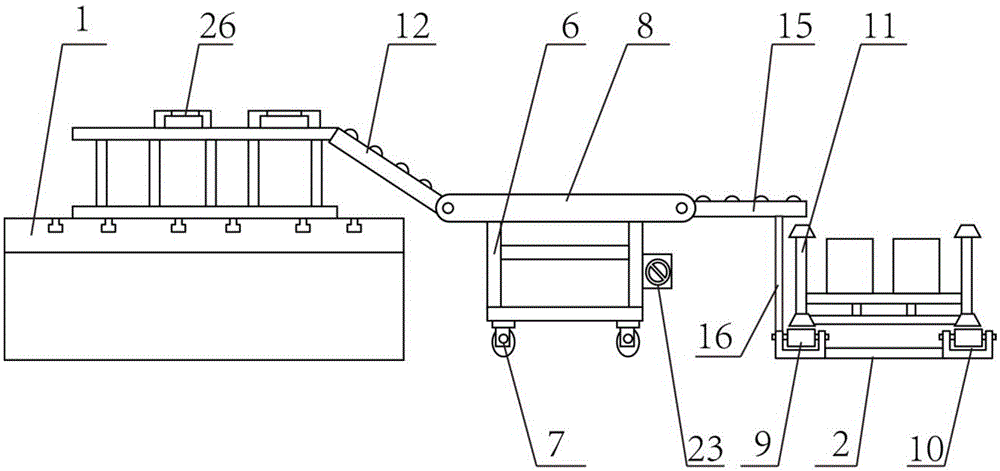
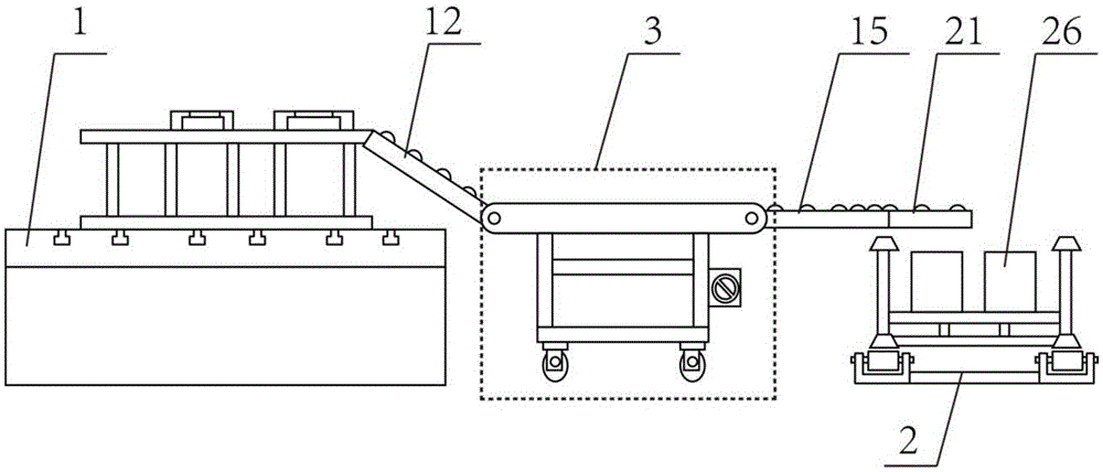
[0032] A discharge conveying device for a stamping production line, comprising a discharge platform 1 and a conveying track 2, the discharge conveying device also includes a conveying trolley 3, the height of the discharge platform 1 is greater than the height of the conveying trolley 3, and the discharge platform 1 Including a support platform 4 and a roller I5 arranged on the support platform 4, the transfer trolley 3 includes a car body 6, wheels 7 arranged under the car body 6 and a conveyor belt 8 arranged on the car body 6, and the transfer track 2 is provided with two rows of rollers, namely roller II 9 and roller III 10, and the transfer track 2 is also provided with a transfer box 11, the height of the transfer box 11 is smaller than the height of the transfer trolley 3, and the discharge platform 1 There is a mobile platform I12 between the transmission trolley 3, and the mobile platform I12 is set obliquely. The left end of the mobile platform I12 rests on the discha...

Embodiment 2

[0036] A method for using a discharge conveying device of a stamping production line, comprising the following steps:

[0037] (1) The stamping part 26 moves to the left end of the mobile platform I through the roller I, and under the action of the inclination angle of the mobile platform I and the transmission shaft I on the mobile platform I, the stamping part slides from the left end of the mobile platform I to the right end of the mobile platform I;

[0038] (2) The stamping parts fall on the conveyor belt of the transmission trolley, and move to the mobile platform II under the drive of the conveyor belt. Under the action of the transmission shaft II, the stamping parts move to the end of the fixed transmission shaft II, and fall into the transmission box close to the transmission trolley On one side, at this time, the movable transmission shaft II does not move relative to the fixed transmission shaft II under the action of the limit device.

Embodiment 3

[0040] When the transfer box is full near the side of the transfer trolley, the method of using the discharge transfer device of the stamping production line includes the following steps:

[0041] (1) The stamping part 26 moves to the left end of the mobile platform I through the roller I, and under the action of the inclination angle of the mobile platform I and the transmission shaft I on the mobile platform I, the stamping part slides from the left end of the mobile platform I to the right end of the mobile platform I;

[0042](2) The stamping parts fall on the conveyor belt of the transmission trolley, and move to the mobile platform II under the drive of the conveyor belt. At this time, the limit device loses the limit control of the movable transmission shaft II under the control of the control device, and the movable transmission shaft Driven by the stamping parts, II moves towards the transfer box, and its right end extends above the center of the transfer box, and the ...


PUM


Abstract

The invention discloses a discharging and conveying device of a punching production line. The discharging and conveying device comprises a discharging platform and a conveying rail. The discharging and conveying device further comprises a conveying trolley. The discharging platform comprises a supporting table and rollers I arranged on the supporting table. Two rows of rollers, namely rollers II and rollers III, are arranged on the conveying rail. A movable platform I is arranged between the discharging platform and the conveying trolley. The left end of the movable platform I is lapped on the discharging platform, and the right end of the movable platform I is connected with the conveying trolley through fixing bolts I. A plurality of rows of conveying shafts I are arranged on the movable platform I. A movable platform II is arranged between the conveying trolley and the conveying rail. The left end of the movable platform II is connected with the conveying trolley through fixing bolts II, and the right end of the movable platform II is located above the rollers II. According to the discharging and conveying device, the conveying trolley is additionally arranged and located between the discharging platform and the conveying rail, and seamless butt joint of the discharging platform and the conveying rail is achieved.

Description

technical field [0001] The invention belongs to the field of conveying devices, in particular to a discharge conveying device for a stamping production line. technical background [0002] In my country's automobile industry, more than 60% of the parts of the automobile itself need to be stamped to complete, including the outer panel of the reflector, as large as the outer shell of the vehicle, all of which require stamping to varying degrees. Stamping is widely used in the automobile manufacturing industry due to its high efficiency, energy saving and low cost. The rapid development of the automobile industry is inseparable from the development of the stamping industry. [0003] The punching machine is mainly composed of a feeding and discharging mechanism, a transmission mechanism, and a stamping mechanism. The feeding and discharging mechanism is used for feeding and returning materials. The workpiece is sent to the discharge mechanism to be sent out. However, the existin...

Claims


Application Information

Patent Timeline
Patent Type & Authority Applications(China)
IPC IPC(8): B65G37/00B65G41/00
CPCB65G37/00B65G41/007
Inventor 姚富娟李守刚
Owner TIANJIN HENGXING MECHANICAL EQUIP
Why Eureka
Try Eureka