Connecting device of drainage pipeline and inspection well

A technology for connecting devices and drainage pipes, which is applied in the field of drainage engineering, can solve the problems of high maintenance costs, large labor consumption of materials, and high construction costs, and achieve the effects of simplifying installation steps, avoiding seepage problems, and improving installation efficiency

Active Publication Date: 2016-05-04
胡皓勇
View PDF4 Cites 2 Cited by
  • Summary
  • Abstract
  • Description
  • Claims
  • Application Information

AI Technical Summary

Problems solved by technology

[0004] In the above-mentioned anti-seepage treatment, the concrete (mortar) filled in the gap between the outer wall of the pipeline and the inspection well is not easy to vibrate and compact, the actual construction effect is poor, and it is easy to seep water during use; and in the actual treatment, it is greatly affected by the construction process and needs to be first To install the pipeline, the inspection well can only be constructed after the pipeline installation is completed, the construction requirements are high, and the construction period is long; the anti-seepage treatment process between the pipeline and the inspection well is complicated, the consumption of materials and labor is large, the construction period is long, and the construction cost is high , In addition, the replacement of drainage system pipes is difficult and the maintenance cost is high

Method used


Image

  • Connecting device of drainage pipeline and inspection well
  • Connecting device of drainage pipeline and inspection well
  • Connecting device of drainage pipeline and inspection well

Examples


Embodiment Construction

[0031] The following will clearly and completely describe the technical solutions in the embodiments of the present invention with reference to the accompanying drawings in the embodiments of the present invention. Obviously, the described embodiments are only some, not all, embodiments of the present invention. Based on the embodiments of the present invention, all other embodiments obtained by persons of ordinary skill in the art without making creative efforts belong to the protection scope of the present invention.

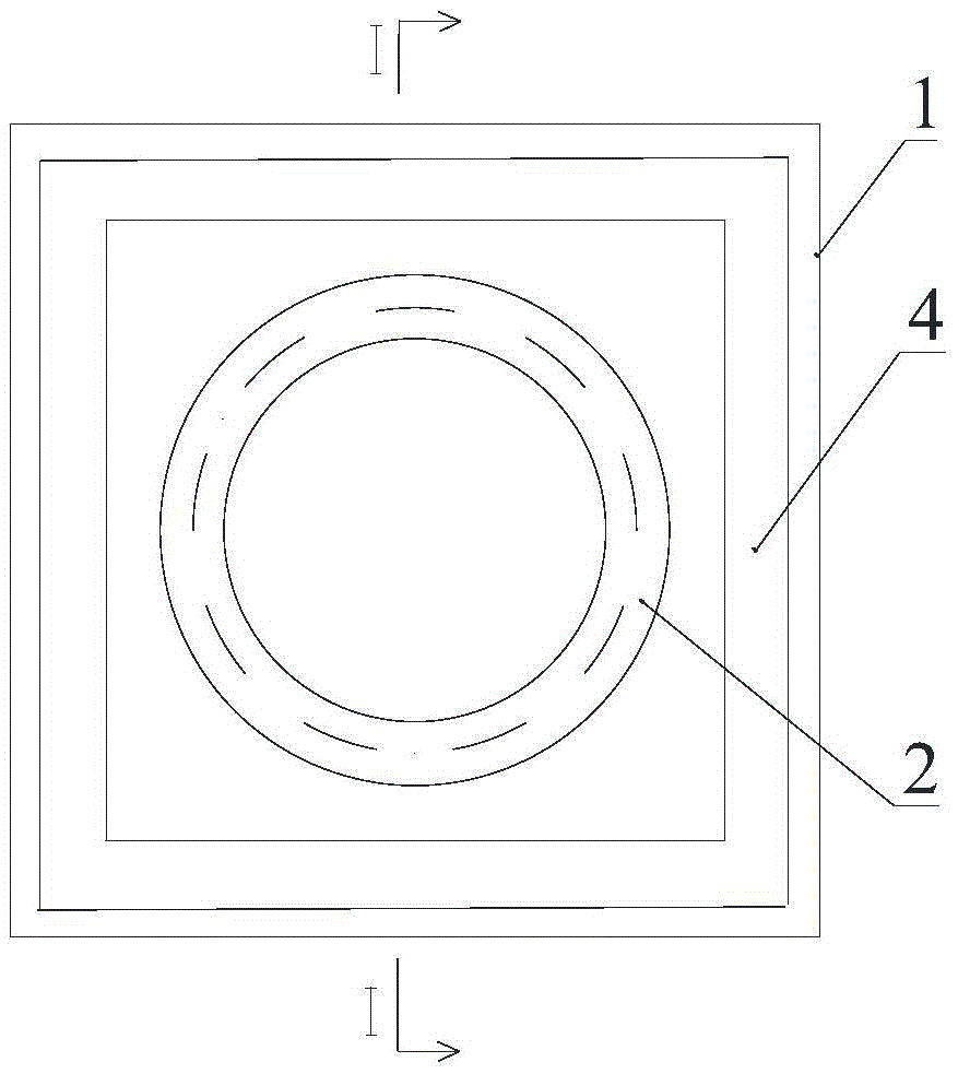
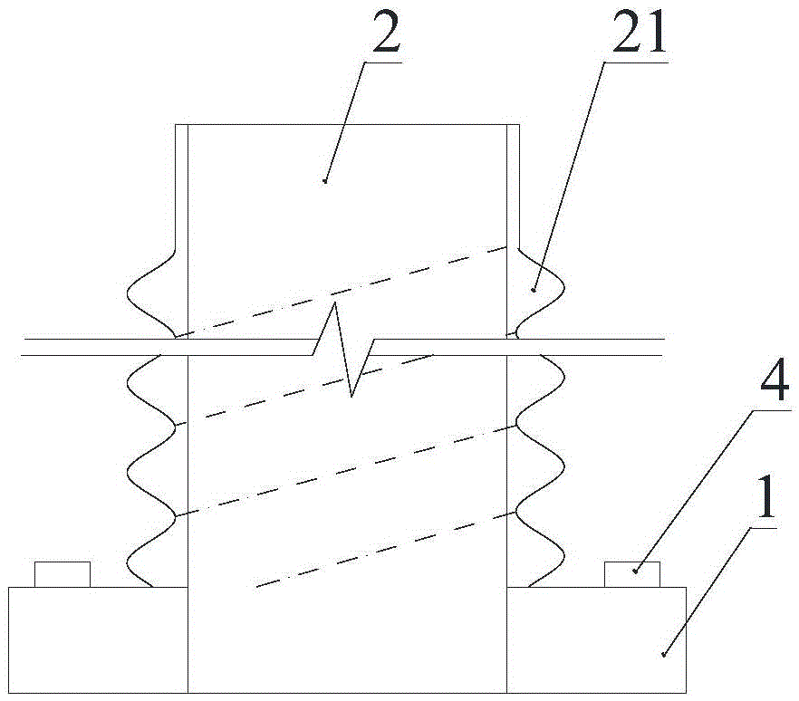
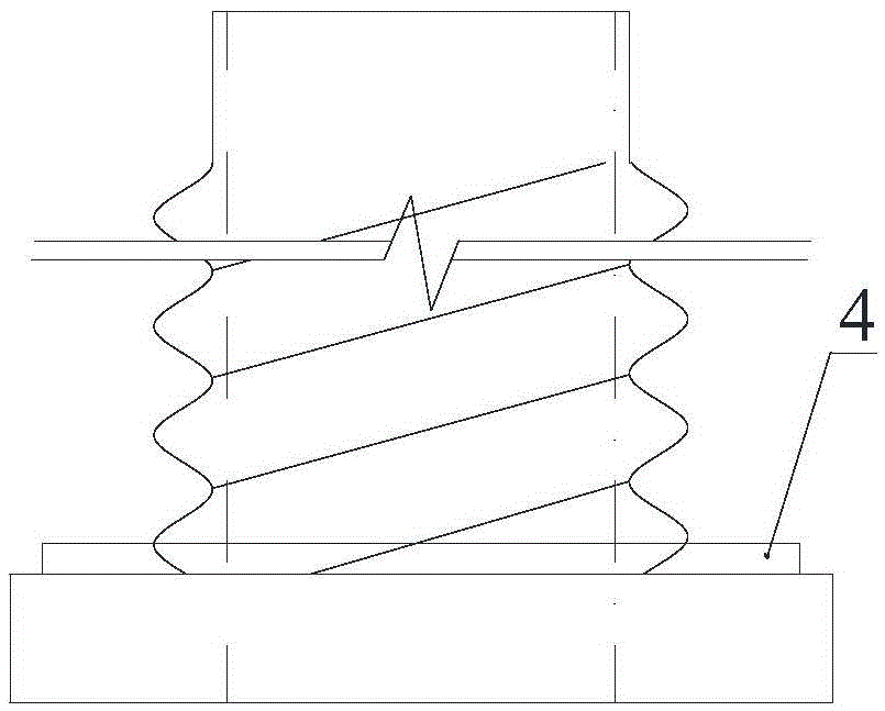
[0032] See Figure 1 to Figure 7 , The connection device between the drainage pipe and the inspection well provided by the embodiment of the present invention includes a bottom plate 1, a column 2 and a snap ring 3, wherein the bottom plate 1 and the column 2 are both ring-shaped, and preferably the inner circle of the ring is circular , and the inner diameters of the annular structures of the two are the same, thereby playing the role of drainage pipes. The ...


PUM


Abstract

The invention discloses a connecting device of a drainage pipeline and an inspection well. The connecting device comprises an annular base plate, an annular upright post and a clamping ring, wherein a waterstop is arranged on the base plate; the first end of the annular upright post is fixedly installed on the base plate, external threads are formed on the upright post, the second end of the upright post is used for being connected with the drainage pipeline, and the upright post and the waterstop are positioned on the same side of the base plate; the clamping ring is matched with the upright post, and internal threads which are matched with the external threads are formed on the inner wall of the clamping ring. During installation, the upright post is installed in the inspection well, and the waterstop on the base plate is positioned between the base plate and the inner wall of the inspection well, so that the problem of permeation is effectively solved. The upright post has the function of the drainage pipeline due to an annular structure, in addition, the external threads on the upright post can be matched with the internal threads on the clamping ring, therefore, gaps do not need to be filled with mortar during installation, and effective installation can be realized only by virtue of thread fitting, thereby simplifying installation steps of the connecting device and improving the installation efficiency.

Description

technical field [0001] The invention relates to the technical field of drainage engineering, in particular to a connection device between a drainage pipe and an inspection well. Background technique [0002] In the drainage project, the gap between the pipeline and the inspection well needs to be treated with anti-seepage. [0003] The existing anti-seepage treatment method for gaps between pipe wells is: using cement mortar, concrete, sealing rings and other materials to fill the gap between the outer wall of the pipe and the inspection well. [0004] In the above-mentioned anti-seepage treatment, the concrete (mortar) filled in the gap between the outer wall of the pipeline and the inspection well is not easy to vibrate and compact, the actual construction effect is poor, and it is easy to seep water during use; and in the actual treatment, it is greatly affected by the construction process and needs to be first To install the pipeline, the inspection well can only be con...

Claims


Application Information

Patent Timeline
Patent Type & Authority Applications(China)
IPC IPC(8): E02D29/12
CPCE02D29/12
Inventor 胡皓勇冉黎明
Owner 胡皓勇
Why Eureka
Try Eureka