Check patentability & draft patents in minutes with Patsnap Eureka AI!

Composite control valve group, control loop and hoisting translation control method of crane

A compound control and valve group technology, which is applied in the direction of mechanical equipment, transportation and packaging, load hanging components, etc., can solve the problems of low compound operation level of operators, uneven load of a single crane, rollover, etc.

Active Publication Date: 2017-05-31
ZOOMLION HEAVY IND CO LTD
View PDF7 Cites 0 Cited by
  • Summary
  • Abstract
  • Description
  • Claims
  • Application Information

AI Technical Summary

Problems solved by technology

However, the trajectory relationship between the luffing hoisting and descending angle and the hoisting and hoisting height is nonlinear, and due to the differences in the parameters of the motor and the reducer, the relationship between the trajectory of the compound action of the luffing and the main hoist is different from that of the luffing and auxiliary hoisting. Composite action trajectory relationship is not the same
When carrying out a large number of horizontal mobile hoisting installation conditions of a single load, due to reasons such as the low level of combined operation of the operator, the hoisting work efficiency will be low
When carrying out joint lifting and horizontal moving hoisting installation conditions of two or more cranes, the height and synchronization of hoisting heavy objects, work safety and hoisting will be seriously affected due to the operator's compound operation level and inconsistent action coordination. More seriously, it will lead to uneven load and overload of a single crane, which will cause serious safety accidents such as rollover

Method used


Image

  • Composite control valve group, control loop and hoisting translation control method of crane
  • Composite control valve group, control loop and hoisting translation control method of crane
  • Composite control valve group, control loop and hoisting translation control method of crane

Examples


Embodiment Construction

[0046] The specific embodiments of the present invention will be described in detail below with reference to the accompanying drawings. It should be understood that the specific embodiments described herein are only used to illustrate and explain the present invention, but not to limit the present invention.

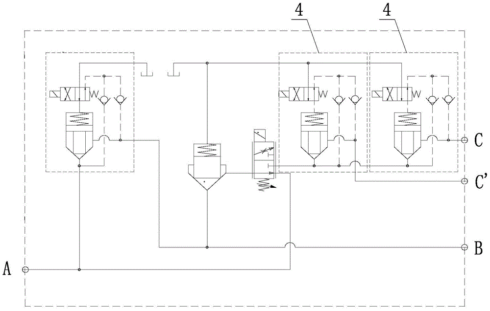
[0047] like figure 1 or figure 2 As shown, the present invention first provides a compound control valve group, the compound control valve group has a first oil port A, a second oil port B and an oil branch port C, and the first oil port A and the second oil port B are An oil inlet on-off valve 1 is provided in the first internal oil circuit L1 connected to each other, and an oil return check valve 2, The proportional flow valve 3 and the oil separation on-off valve 4, the forward port of the oil return check valve 2 is hydraulically connected to the second oil port B, and the reverse port is hydraulically connected to the inlet port of the proportional flow valve 3. ...


PUM


Abstract

The invention discloses a compound control valve set, a control loop and a lifting and horizontally-moving control method for a crane. A first inner oil line (L1) connected between a first oil opening (A) and a second oil opening (B) of the valve set is internally provided with an oil inlet on-off valve (1). A second inner oil line (L2) connected between the second oil opening and an oil distribution opening (C) is internally provided with an oil return one-way valve (2), a proportional flow valve (3) and an oil distribution on-off valve (4) in sequence. The proportional flow valve is used for proportionally distributing pressure oil of an oil opening in the inlet end to a proportional oil return opening and a proportional flow distribution opening in the outlet end of the proportional flow valve. In the compound control hydraulic loop, two working loops can be correlated through an oil distribution oil line and the oil distribution opening, relevant control over the amplitude and the winching in the crane of an automobile is achieved, and therefore the horizontally-moving movement of lifted weights is achieved; and in addition, independent control over the amplitude and the winching can be achieved, and therefore operation is convenient, and the requirement for the technique of operation personnel is lowered.

Description

technical field [0001] The invention belongs to the field of cranes, and in particular relates to a hydraulic circuit and a control valve group thereof for compositely controlling the luffing and hoisting of a boom. Background technique [0002] In the hoisting condition of the truck crane, the operator is often required to operate the control handle separately to realize the compound action of the luffing and the main hoist or the compound action of the luffing and the auxiliary hoist, so as to achieve the purpose of hoisting heavy objects for horizontal movement. Among them, the electro-hydraulic control systems for luffing and hoisting actions are independent of each other. The hydraulic oil source of the luffing electro-hydraulic control system is directly connected to the luffing cylinder after being selected by the main valve luffing plate, and the hoisting electro-hydraulic control system The hydraulic oil source is directly connected to the hoisting motor after the r...

Claims


Application Information

Patent Timeline
Patent Type & Authority Patents(China)
IPC IPC(8): F15B13/08B66C13/20
CPCB66C13/20F15B13/0832
Inventor 黄杰刘伟罗贤智郭纪梅李英智
Owner ZOOMLION HEAVY IND CO LTD
Features
  • R&D
  • Intellectual Property
  • Life Sciences
  • Materials
  • Tech Scout
  • Unparalleled Data Quality
  • Higher Quality Content
  • 60% Fewer Hallucinations
Learn More