Smart furniture plate of smart home system

A smart home system and smart furniture technology, applied in the direction of thin plate connection, connecting components, mechanical equipment, etc., can solve the problems of damage, inconvenient screw disassembly, easy damage to the board, etc., to avoid damage to objects, improve aesthetics, and firm connection Effect

Inactive Publication Date: 2016-05-04
CHENGDU ZHONGFU LIXIANG TECH
View PDF0 Cites 0 Cited by
  • Summary
  • Abstract
  • Description
  • Claims
  • Application Information

AI Technical Summary

Problems solved by technology

[0002] With the development of society and the popularization of intelligent systems, people's lives are now developing towards intelligence. In smart homes, wardrobes, plank beds, sofas, etc. are becoming more and more intelligent and multi-functional. However, as a panel home, Many of their connection methods are fixed by screws. The screw connection is generally fixed by screws at the joint, which leads to the following two problems: Problem 1. When the screws need to be replaced after fixing or when the home needs maintenance, the screws should be removed. Inconvenient and easy to damage the board, resulting in increased maintenance costs, and the screw connection is also extremely unstable. After a long time of use, the board is prone to gaps and shaking problems; problem 2, the screw head is generally exposed after the screw is fixed On the outer surface of the board, it is extremely unsightly. At the same time, in wardrobes, wooden beds and other households, the screw heads can easily catch the bed quilt or clothing, thereby damaging the internal objects or the external wrapping fabric, causing damage.

Method used


Image

  • Smart furniture plate of smart home system
  • Smart furniture plate of smart home system
  • Smart furniture plate of smart home system

Examples


Embodiment 1

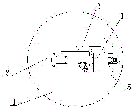
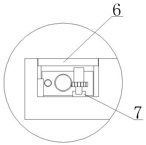
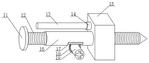
[0016] Such as Figure 1-Figure 3 As shown, the smart furniture board of the smart home system includes a square board 4, the corner of the square board 4 is provided with a built-in groove 3, and a board connector 1 is fixed in the built-in groove 3; the board connector 1 includes Fixing block 15 and fixing screw 12, the side of described fixing block 15 is provided with guide sleeve 16, described fixing screw 12 is threadedly connected with fixing block 15 through guiding sleeve 16, and described fixing screw 12 penetrates fixing block 15 and square plate body After 4, extend the square plate body 4; the built-in groove 3 is also provided with a block 2 for clamping the plate body connector 1; the square plate body 4 is located on the side where the fixing screw 12 extends and a positioning plate 5 is also provided ; The built-in tank 3 is also provided with a detachable tank cover 6 .

[0017] The working principle of this embodiment is: first, the square plate body 4 corr...

Embodiment 2

[0021] In this embodiment, the board connector is optimized on the basis of Embodiment 1, specifically: the board connector 1 also includes a screw adjustment column 19, and the screw adjustment column 19 is provided with a gear 18 threadedly engaged with the fixing screw 12, A notch 17 is arranged on the side of the guide sleeve 16, and the gear 18 is arranged on the outside of the notch 17 and is threadedly engaged with the fixing screw 12 to form a movable mechanism in which the rotation of the gear 18 drives the fixing screw 12 to move axially. A rotating seat 7 is provided, and the screw adjusting column 19 is rotatably arranged in the rotating seat 7 .

[0022] In this embodiment, the screw adjustment column 19 is provided, and the gear 18 is threadedly engaged with the fixing screw 12. By rotating the screw adjustment column 19, the fixing screw 12 can be rotated to move left and right along the axial direction, thereby conveniently completing the advance and retreat of ...

Embodiment 3

[0025] In this embodiment, the following structure is added on the basis of embodiment 1 or embodiment 2: the fixed block 15 is located on the side of the guide sleeve 16 and a card seat 14 is also provided, and a detachable top column 13 is arranged in the card seat 14, so that One end of the fixing screw 12 located at the guide sleeve 16 is also provided with a retaining ring 11, the retaining ring 11 can limit the horizontal movement of the fixing screw 12 through the push post 13.

[0026] In this embodiment, by setting the detachable top post 13, according to the installation requirements and the thickness of the connecting plate, the top post 13 of different lengths is used, and the top post 13 is used to resist the retaining ring 11, so that the horizontal movement of the fixing screw 12 can be restricted to ensure The drilling depth of the fixing screw 12 prevents the fixing screw 12 from drilling through the connecting plate, and at the same time, it is convenient for ...


PUM


Abstract

The invention relates to a smart furniture plate of a smart home system. The smart furniture plate comprises a square plate body, wherein a built-in slot is formed in a corner of the square plate body, and a plate body connector is fixed in the built-in slot; the plate body connector comprises a fixing block and a fixing screw, a guide sleeve is arranged on the side surface of the fixing block, the fixing screw is in threaded connection with the fixing block through the guide sleeve, and the fixing screw penetrates through the fixing block and the square plate body and extends out of the square plate body; a clamping block used for clamping the plate body connector is further arranged in the built-in slot; a positioning plate is further arranged on the side surface, where the fixing screw extends out, of the square plate body; a detachable slot cover is further arranged on the built-in slot. The plate body connector is arranged in the plate body without being exposed out, the attractiveness of home furnishing is improved, the situation that the exposed screw hooks an article in furniture is avoided, damage to the article is avoided, besides, the connector is firm in connection and convenient to use, and the plate body cannot loosen even if the connector is used for a long time.

Description

technical field [0001] The invention relates to a home panel, which belongs to the field of smart home, and more specifically relates to a smart furniture panel of a smart home system. Background technique [0002] With the development of society and the popularization of intelligent systems, people's lives are now developing towards intelligence. In smart homes, wardrobes, plank beds, sofas, etc. are becoming more and more intelligent and multi-functional. However, as a panel home, Many of their connection methods are fixed by screws. The screw connection is generally fixed by screws at the joint, which leads to the following two problems: Problem 1. When the screws need to be replaced after fixing or when the home needs maintenance, the screws should be removed. Inconvenient and easy to damage the board, resulting in increased maintenance costs, and the screw connection is also extremely unstable. After a long time of use, the board is prone to gaps and shaking problems; p...

Claims


Application Information

Patent Timeline
IPC IPC(8): F16B5/02
CPCF16B5/0225F16B5/025F16B5/0291
Inventor 汪海李国
Owner CHENGDU ZHONGFU LIXIANG TECH
Why Eureka
Try Eureka