
Industrial furnace with liftable dust-collecting furnace cover

A technology for industrial furnaces and furnace covers, applied in the field of heat treatment, can solve the problems of inability to apply heat treatment production lines, unfavorable health of production personnel, and long circulation time of toxic gases, and achieves a technology that is beneficial to workers' health, good suction effect and simple structure. Effect

Active Publication Date: 2016-05-04
嘉兴乐创紧固件科技有限公司
View PDF5 Cites 1 Cited by
  • Summary
  • Abstract
  • Description
  • Claims
  • Application Information

AI Technical Summary

Problems solved by technology

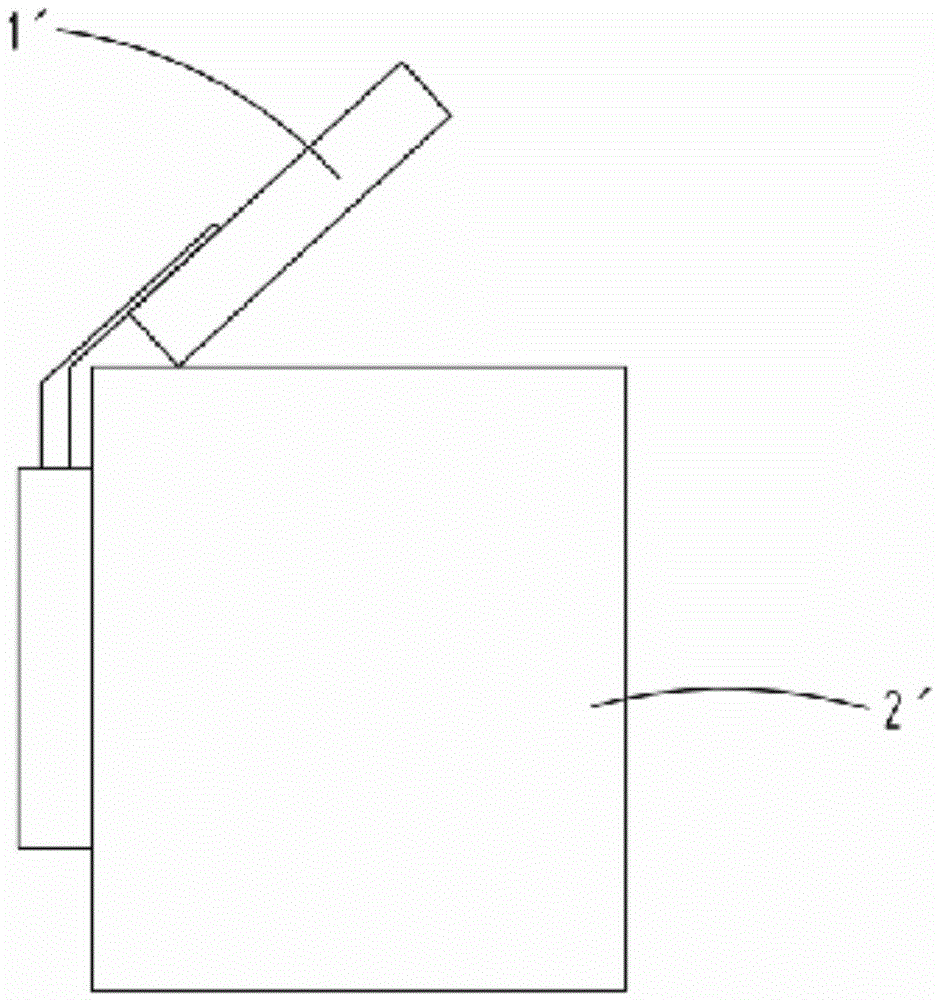
like figure 1 As shown, the furnace cover 1' of the existing heat treatment furnace is arranged above the furnace mouth, and can be opened or closed by the lifting mechanism. A large amount of toxic gas such as smoke and dust will be directly diffused into the production workshop. Although the toxic gas diffused into the workshop is finally discharged through the exhaust channel set on the top of the workshop, the circulation time of toxic gas in the workshop is long, polluting The production environment in the workshop is not conducive to the health of the production personnel. In addition, when the workpiece is hoisted in or out, the material frame often interferes with the furnace cover and cannot be put in, which hinders the production progress and cannot be applied to the heat treatment production line. Medium, limited scope of application

Method used


Image

  • Industrial furnace with liftable dust-collecting furnace cover
  • Industrial furnace with liftable dust-collecting furnace cover
  • Industrial furnace with liftable dust-collecting furnace cover

Examples


Embodiment 1

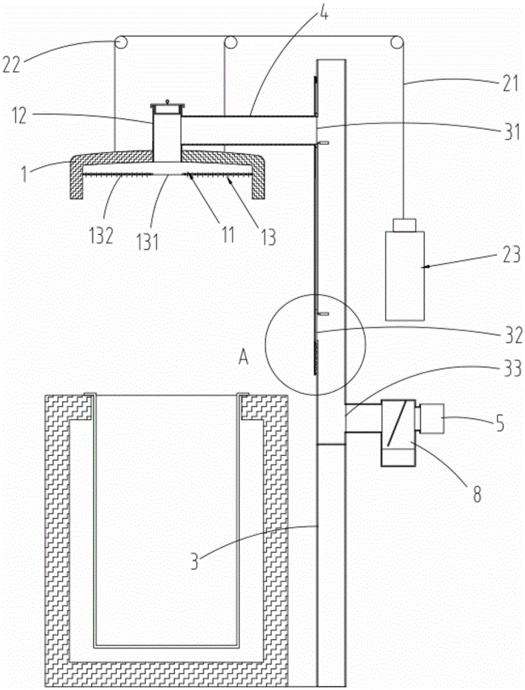
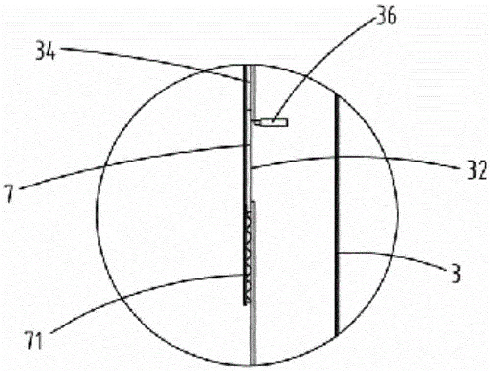
[0032] Such as figure 2 As shown, the present invention provides an industrial furnace with a liftable dust-absorbing furnace cover, including a furnace body 9, a furnace cover 1 arranged on the furnace mouth of the furnace body 9 that can be opened or closed, and a lifting device for lifting the furnace cover 1. Mechanism 2, the inner wall of the furnace cover 1 is formed with a semi-closed cavity 11, and the top of the furnace cover 1 is provided with a salt adding channel 12 communicating with the cavity 11. 9. The fixed flue gas pipe 3 next to it and the movable flue gas pipe 4 with one end connected to the salt adding channel 12 are provided with a first flue gas inlet 31 and a second flue gas inlet 32 ​​communicating with the inside of the fixed flue gas pipe 3. and the flue gas outlet 33, the flue gas outlet 33 is connected with a smoking device 5; the end of the movable flue gas pipe 4 can move up and down along the outer wall of the fixed flue gas pipe 3, and the sal...


PUM


Abstract

The invention relates to an industrial furnace with a liftable dust-collecting furnace cover. The industrial furnace comprises a furnace body, the furnace cover, and a lifting mechanism for lifting the furnace cover, wherein a semienclosed cavity is formed on the inner wall of the furnace cover; a salt adding passage is formed in the top of the furnace cover; a first flue gas inlet, a second flue gas inlet and a flue gas outlet which are communicated with the inside of a fixed flue gas pipeline are formed in the fixed flue gas pipeline; the flue gas outlet is connected with a flue gas pumping device; the end part of a movable flue gas pipeline can move up and down along the outer wall of the fixed flue gas pipeline; the salt adding passage is communicated with the first flue gas inlet or the second flue gas inlet through the movable flue gas pipeline; a crucible is arranged at the inner part of the furnace body; the height difference of the first flue gas inlet and the second flue gas inlet meets the condition that when the furnace cover is opened, a workpiece to be processed can be hung into the crucible. The condition of interference generated in materials and the furnace cover when the workpiece is hung into the furnace body is avoided, flue gas dispersed in the furnace body can be concentrated and pumped no matter whether the furnace cover is opened or closed, the workshop environment can be improved, and the health of workers are benefited.

Description

technical field [0001] The invention relates to the technical field of heat treatment, in particular to an industrial furnace with a liftable dust suction furnace cover. Background technique [0002] In the field of heat treatment technology, the collection and discharge of smoke and dust is one of the important links in the production process. Such as figure 1 As shown, the furnace cover 1' of the existing heat treatment furnace is arranged above the furnace mouth, and can be opened or closed by the lifting mechanism. A large amount of toxic gas such as smoke and dust will be directly diffused into the production workshop. Although the toxic gas diffused into the workshop is finally discharged through the exhaust channel set on the top of the workshop, the circulation time of toxic gas in the workshop is long, polluting The production environment in the workshop is not conducive to the health of the production personnel. In addition, when the workpiece is hoisted in or ou...

Claims


Application Information

Patent Timeline
IPC IPC(8): F27D1/18F27D17/00
CPCF27D1/18F27D17/001F27D2001/1825
Inventor 叶玉芳叶华健
Owner 嘉兴乐创紧固件科技有限公司
Learn More