
Camera module group power-on time sequence testing device and method

A camera module and power-on sequence technology, which is applied to measuring devices, measuring electricity, and measuring electrical variables, etc., can solve the problems of cumbersome and inconvenient operation and low test efficiency

Active Publication Date: 2016-05-04
GOERTEK OPTICAL TECH CO LTD
View PDF6 Cites 9 Cited by
  • Summary
  • Abstract
  • Description
  • Claims
  • Application Information

AI Technical Summary

Problems solved by technology

[0005] The purpose of the present invention is to provide a camera module power-on timing test device, which aims to solve the problem of testing the power-on sequence of the camera module through an oscilloscope in the prior art. lower question

Method used


Image

  • Camera module group power-on time sequence testing device and method
  • Camera module group power-on time sequence testing device and method

Examples


Embodiment Construction

[0032] In order to make the object, technical solution and advantages of the present invention clearer, the present invention will be further described in detail below in conjunction with the accompanying drawings and embodiments. It should be understood that the specific embodiments described here are only used to explain the present invention, not to limit the present invention.

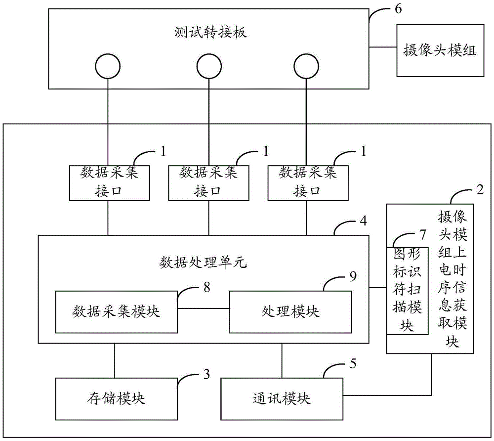
[0033] figure 1 It shows a structural block diagram of the camera module power-on sequence test device provided by the present invention. For the convenience of description, only the parts related to the present invention are shown in the figure.

[0034] The camera module power-on sequence test device includes several data acquisition interfaces 1, camera module power-on sequence information acquisition module 2, storage module 3, data processing unit 4 and communication module 5, wherein:

[0035] Several data acquisition interfaces 1 are used to collect the voltage parameters of each power-on c...


PUM


Abstract

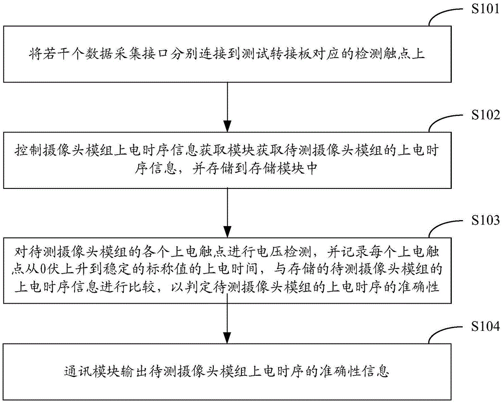
The invention relates to the technical field of camera module group testing, and provides a camera module group power-on time sequence testing device and method. The device comprises a plurality of data collection interfaces, a camera module group power-on time sequence information obtaining module, a storage module, a data processing unit, and a communication module. The data processing unit enables the power-on time sequence information, obtained by the camera module group power-on time sequence information obtaining module, of a to-be-tested camera module group to be stored in the storage module, calculates the power-on time, collected by the plurality of data collection interfaces, of each power supply of the to-be-tested camera module group, and compares the power-on time with the power-on time sequence information stored in the storage module, so as to determine the accuracy of power-on time sequence of the to-be-tested camera module group. The communication module outputs the accuracy information of the power-on time sequence of the to-be-tested camera module group, thereby achieving the automatic testing of the power-on time sequence of the to-be-tested camera module group. The device is simple in operation, and is higher in testing efficiency.

Description

technical field [0001] The invention belongs to the technical field of camera module testing, in particular to a camera module power-on sequence testing device and testing method. Background technique [0002] The camera module (CompactCameraModule, CCM) needs to test the power-on sequence in the R & D and design stage to judge whether the power-on sequence of each power supply meets the design requirements of the product. At present, an oscilloscope is generally used to complete the test of the CCM power-on sequence. The specific method is: [0003] The tester manually connects the test terminal of the oscilloscope to the test contact of the power supply of the test adapter board, and then reads the power-on delay of each power supply on the oscilloscope, and then judges based on the power-on sequence information of the camera module. Whether the power-on delay meets the power-on requirements, so as to determine whether the power-on sequence of the entire camera module mee...

Claims


Application Information

Patent Timeline
IPC IPC(8): G01R31/3177
CPCG01R31/3177
Inventor 李龙
Owner GOERTEK OPTICAL TECH CO LTD
Learn More