
LED display screen alternative point collection correction method

A technology of LED display screen and calibration method, which is applied in the direction of static indicators, instruments, etc., can solve the problems of reducing image brightness, increasing single LED, moiré, etc., so as to reduce the difficulty of adjustment and reduce the difficulty of defocus adjustment , Saving the time-consuming effect of calibration

Active Publication Date: 2016-05-04
XIAN NOVASTAR TECH
View PDF8 Cites 15 Cited by
  • Summary
  • Abstract
  • Description
  • Claims
  • Application Information

AI Technical Summary

Problems solved by technology

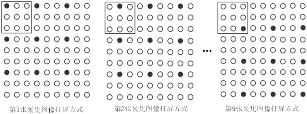
[0005] However, this method also has its bottleneck. On the one hand, as the cell size of the interval increases, the number of lights on a single captured image will decrease exponentially, and the brightness of a single captured image will also decrease exponentially. Resolution screen 10*10 point-by-point correction brightness is 100 times lower than non-point-by-point correction, so when the cell size of every point increases to a certain extent, the brightness of a single captured image cannot meet the point-by-point correction requirements; on the other hand When the resolution of the single acquisition screen continues to increase, the number of effective CCD pixels occupied by a single LED for image acquisition will continue to decrease, which is prone to low acquisition accuracy or moiré. Therefore, it is necessary to increase the defocus blur during acquisition. The number of effective CCD pixels occupied by each LED, and defocus blur will also reduce the brightness of the image

Method used


Image

  • LED display screen alternative point collection correction method
  • LED display screen alternative point collection correction method
  • LED display screen alternative point collection correction method

Examples


Embodiment Construction

[0024] In order to make the above objects, features and advantages of the present invention more comprehensible, specific implementations of the present invention will be described in detail below in conjunction with the accompanying drawings.

[0025] The embodiment of the present invention aims at the bottleneck problem of the current point-by-point collection and correction method, and proposes a method for collecting and correcting LED display screens with multiple lights at several points. The effective utilization of the camera's CCD ensures that the brightness of a single image meets the requirements and at the same time reduces the difficulty of adjusting the parameters of the image acquisition equipment. In addition, it also reduces the difficulty of adjusting the defocus, making the acquisition and correction of multiple lamps at intervals more efficient. In the calibration of the high-resolution LED display, it saves a lot of time-consuming calibration.

[0026] Spe...


PUM


Abstract

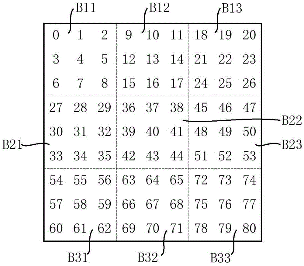
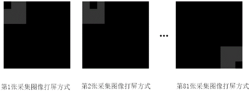
The invention relates to an LED display screen alternative point collection correction method, comprising steps of virtually partitioning an area to be corrected into a plurality of alternative point unit cell, and determining the image screen correction mode which is that LED lamps of the same color in a plurality of LED pixels in each alternative point unit cell are controlled to be illuminated for each time. Aiming for the bottleneck problem of the alternative point collection correction mode, the invention provides an LED display screen alternative point multi-lamp collection correction method, which improves the photosensitive members of the image collection device, like the effective utilization rate of the camera CCD through increasing the LED pixel quantity on a single collection image, guarantees that the brightness collected by the single collection image while reducing the complexity of regulating the parameters by the collection device, reduces the difficulty of regulating the defocusing, enables the alternative point multi-lamp collection correction mode to be highly effectively applied into the correction of a greater resolution ratio LED display screen, and saves the substantial time spending on correction.

Description

technical field [0001] The invention relates to the technical field of LED display correction, in particular to a method for collecting and correcting LED display screens at intervals. Background technique [0002] In recent years, the development of LED display manufacturing industry at home and abroad has gradually tended to small pitch and super high resolution. These development trends also directly determine that the LED display calibration industry has ushered in new challenges. The so-called small pitch refers to the smaller pitch of LED lights, such as P1.5 means that the pixel pitch is 1.5mm. The ever-shrinking LED spacing means that the display will move from outdoors to indoors, from long-distance viewing to close-distance viewing. In addition, the shrinking LED spacing also increases the resolution of screens with the same physical size, such as 2K, 4K screen body. [0003] When the LED display calibration industry is facing the challenges of small pitch and su...

Claims


Application Information

Patent Timeline
IPC IPC(8): G09G3/32
CPCG09G3/32G09G2320/0626
Inventor 韩周周晶晶
Owner XIAN NOVASTAR TECH
Learn More