Isolated and connected combination switch

A combination switch and grounding switch technology, applied in the direction of electric switches, air switch components, electrical components, etc., can solve the problems of increasing gas leakage, shortening the service life of equipment, increasing water ingress and leakage, and reducing radial force Effect on airtightness, avoidance of triboelectric discharge phenomenon, and effect of reducing the number of parts

Active Publication Date: 2016-05-04
国电博纳(北京)电力设备有限公司
View PDF6 Cites 5 Cited by
  • Summary
  • Abstract
  • Description
  • Claims
  • Application Information

AI Technical Summary

Problems solved by technology

[0002] The three phases of the isolating combination switch currently used in the market are respectively placed in three mutually independent metal tanks, and are connected through external interphase connecting rods. Due to the exposed interphase connecting rods, it may cause connection problems in harsh environments. Rod icing, corrosion and other issues affect the operating performance; at the same time, because the three phases are placed in three independent metal tanks, the three phases will not be on the same plane during the assembly process, which is not conducive to installation and adjustment
In the current products on the market, the fast earthing switch and the isolating switch are respectively set in two different independent tanks, so that when the two are spliced ​​together, a pot insulator must be added, and a corresponding sealing structure must be added to ensure air tightness. This not only increases the possibility of gas leakage, but also increases the cost of the product.
In addition, in the process of assembling the fast earthing switch and the isolating switch, there will be a fit gap, and sealing rings need to be added separately to prevent the entry of water. The structure is more complicated, which is not conducive to the performance guarantee of the product
[0003] Application publication number CN102024606A discloses a three-position isolating grounding switch. Although the three phases of the isolating grounding switch are all arranged inside the same housing, it is necessary to connect the operating mechanism box externally during the working process and assemble a quick grounding switch At the same time, it still needs to be equipped with shell insulators, contact conductors and other components, which will have a great impact on the airtightness of the entire equipment, greatly increase the possibility of water ingress and leakage, and is very unsightly
During the transmission process of the gear and the rack, the friction will produce fine particle debris, which will slide down to the inside of the housing with the transmission device. Once there is too much debris, friction discharge may occur, which will cause damage to the equipment itself. Severe damage. In addition, if the equipment runs for too long, it will cause debris to accumulate in the small space inside the equipment, which will affect the operation of the equipment and shorten the service life of the equipment.

Method used


Image

  • Isolated and connected combination switch
  • Isolated and connected combination switch
  • Isolated and connected combination switch

Examples


Embodiment Construction

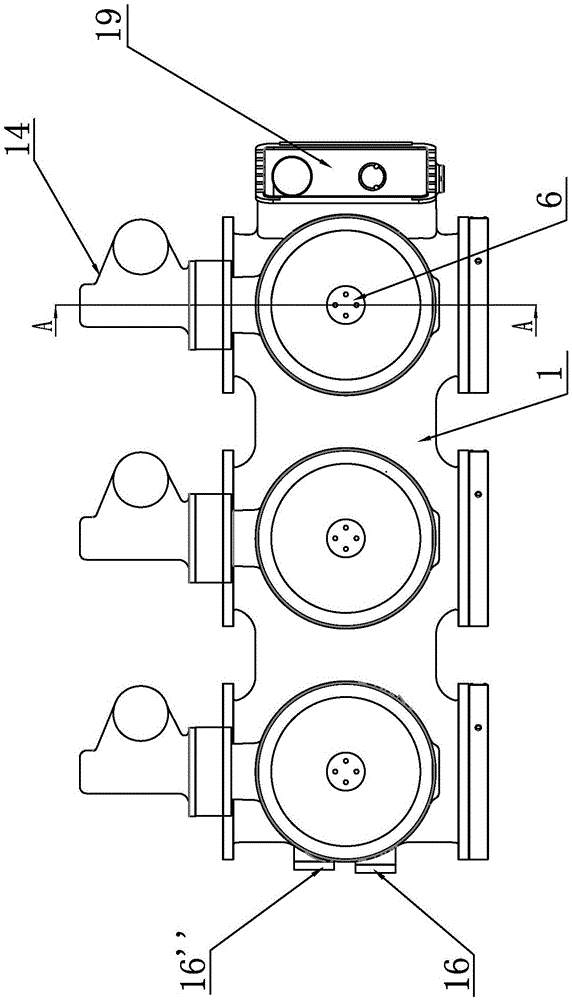
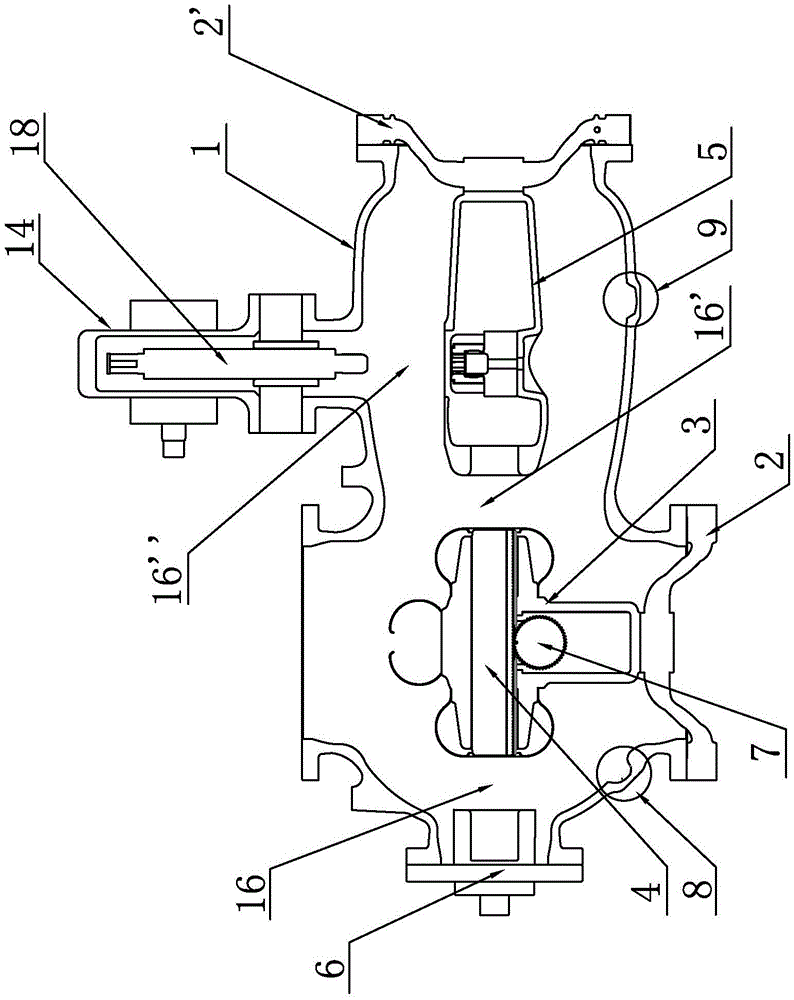
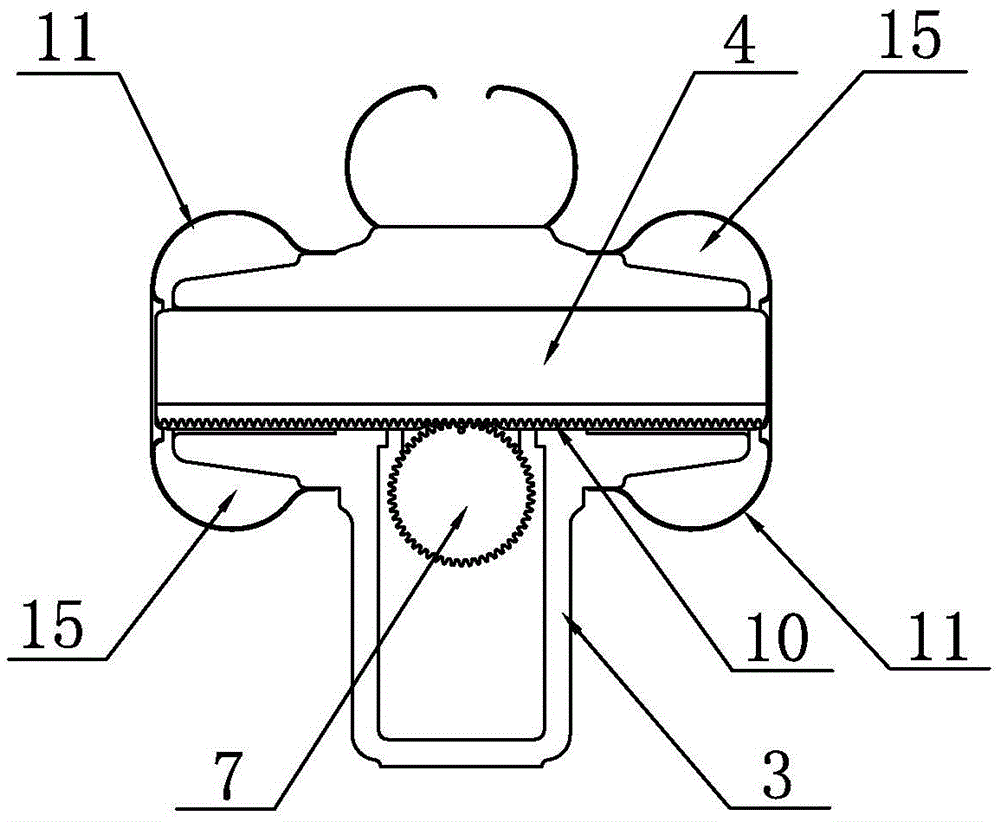
[0020] Such as figure 1 , figure 2 As shown, the isolating combination switch of the present invention includes a housing 1 , a first contact seat 3 , a first conductive rod 4 , a static end part 5 of an isolating switch and a static end part 6 of a grounding switch. The casing 1 is placed in the horizontal direction, and a first cavity is opened inside the casing 1. The grounding switch static end part 6 is installed at the opening of the front end of the casing 1, and the second pot insulator 2 is installed at the opening of the rear end of the casing 1. ', the first cavity inside the housing 1 is provided with a disconnector static end part 5, and the disconnector static end part 5 is fixedly connected with the second pot insulator 2', such as Figure 4 As shown, the static end part 5 of the isolating switch includes a contact seat 12 of the isolating switch and a contact seat 13 of the quick earthing switch. The hole 17, the through hole 17 is located directly above the...


PUM


Abstract

The invention relates to an isolated and connected combination switch, and aims to provide the isolated and connected combination switch with long service life and good air impermeability. The isolated and connected combination switch comprises a shell, a first contact seat and a first conducting rod, wherein a grounding switch static end component is mounted at the front end of the shell, and a second basin-type insulator is mounted at the rear end of the shell; the interior of the shell is provided with an isolating switch static end component and the first contact seat; the isolating switch static end component is fixedly connected with the second basin-type insulator; a first basin-type insulator is mounted at the position of an opening in the bottom end of the shell; the bottom end of the first contact seat is connected with the top end of the first basin-type insulator; the top end of the first contact seat, along the front-and-back direction, is horizontally provided with the first conducting rod; the first conducting rod and the first contact seat are connected through a transmission mechanism; the transmission mechanism is connected with an operating mechanism positioned outside the shell; a shielding case is wrapped and arranged on the outer side of the first contact seat; a first groove is formed in the inner wall of the shell positioned below the grounding switch static end component; and a second groove is formed in the inner wall of the shell positioned below the isolating switch static end component.

Description

technical field [0001] The invention relates to the technical field of high-voltage switches, in particular to a disconnecting combination switch. Background technique [0002] The three phases of the isolating combination switch currently used in the market are respectively placed in three mutually independent metal tanks, and are connected through external interphase connecting rods. Due to the exposed interphase connecting rods, it may cause connection problems in harsh environments. Pole icing, corrosion and other problems affect the operational performance; at the same time, because the three phases are placed in three independent metal tanks, the three phases will not be on the same plane during the assembly process, which is not conducive to installation and adjustment. In the current products on the market, the fast earthing switch and the isolating switch are respectively set in two different independent tanks, so that when the two are spliced ​​together, a pot insu...

Claims


Application Information

Patent Timeline
Patent Type & Authority Applications(China)
IPC IPC(8): H01H9/02H01H31/02
CPCH01H9/02H01H31/02
Inventor 秦宏升
Owner 国电博纳(北京)电力设备有限公司
Why Eureka
Try Eureka