Antenna and antenna control method and device

An antenna and reflector technology, which is applied to antennas, electrical components, etc., can solve the problem of weak omnidirectional antenna gain, and achieve the effect of high gain and good signal coverage.

Inactive Publication Date: 2016-05-04
RUIJIE NETWORKS CO LTD
View PDF12 Cites 8 Cited by
  • Summary
  • Abstract
  • Description
  • Claims
  • Application Information

AI Technical Summary

Problems solved by technology

[0003] In the existing APs that support MU-MIMO technology, the antennas are mostly omnidirectional antennas, and the gain of the omnidirectional antennas is weak

Method used


Image

  • Antenna and antenna control method and device
  • Antenna and antenna control method and device
  • Antenna and antenna control method and device

Examples


Embodiment 1

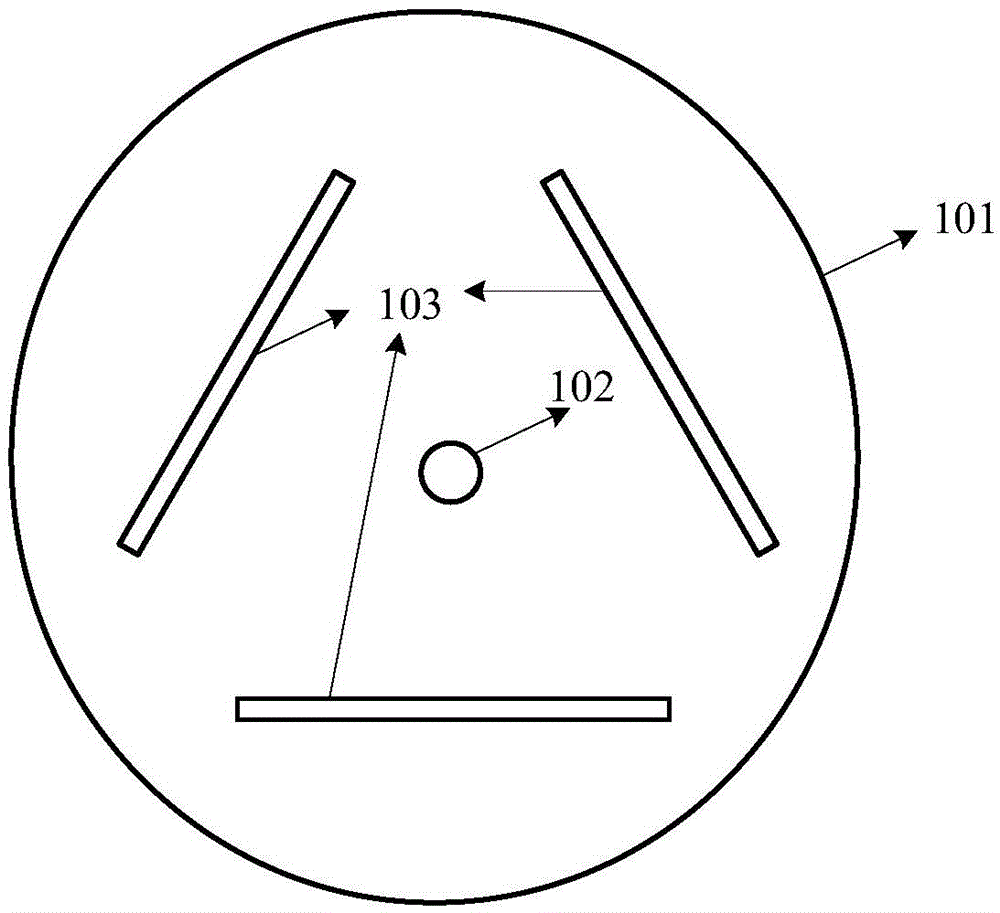
[0056] Such as figure 1 As shown, it is a schematic top view structural diagram of the antenna in Embodiment 1 of the present invention. The antenna may include a substrate 101, a vibrator 102 and three reflectors 103, wherein:

[0057] the vibrator is installed on the substrate;

[0058] The ground point of each reflector in the three reflectors is connected to the ground terminal of the substrate ( figure 1 not shown in);

[0059]The three reflectors are respectively arranged on the vertices of an equilateral triangle with the vibrator as the center of gravity, and the included angle between the reflective surfaces of any two reflectors among the three reflectors is [55°, 65°] between an angle.

[0060] Preferably, an included angle of 60° is selected.

[0061] It should be noted, figure 1 The structures, shapes, and proportional relationships of the middle reflector, the substrate, and the vibrator are only used to illustrate the embodiments of the present invention, a...

Embodiment 2

[0092] Based on the same inventive concept, the embodiment of the present invention also provides an antenna control method, such as Figure 17 Shown is the schematic flow chart of this method, and this method may comprise the following steps:

[0093] Step 1701: Detect the received signal strength of the terminal served by the antenna when the antenna is in a preset state; wherein, the antenna includes a substrate, a vibrator, and three reflectors; the vibrator is installed on the substrate; the The three reflectors are respectively arranged on the vertices of the equilateral triangle with the vibrator as the center of gravity, and the included angle between the reflective surfaces of any two reflectors among the three reflectors is [55,°65° ], and for each reflector, the ground point of the reflector is connected to the ground terminal of the substrate through a switch device, and the switch device is used to control whether the reflector is connected to the ground terminal ...

Embodiment 3

[0103] Based on the same inventive concept, the embodiment of the present invention also provides an antenna control device, such as Figure 18 As shown, the device includes:


PUM


Abstract

The invention discloses an antenna and an antenna control method and device. In the scheme, the antenna comprises a substrate, an oscillator and three reflecting plates, wherein the oscillator is arranged on the substrate, a grounding point of each reflecting plate in the three reflecting plates is connected with a grounding end of the substrate, the three reflecting plates are separately arranged on vertexesof an equilateral triangle taking the oscillator as a gravity center, and an included angle between the reflecting surfaces ofany two reflecting plates in the three reflecting plates is an angle between 55 degrees and 65 degrees. The invention provides the antenna with a three-petal-shaped radiation pattern, the antenna has higher grain than that of an omnidirectional antenna and has better signal coverage range than that of a directional antenna, and thus, the antenna can be applicable for a multi-user multiple-input multiple-output (MU-MIMO) technology better.

Description

technical field [0001] The present invention relates to the technical field of antennas, in particular to antennas, antenna control methods and devices. Background technique [0002] MU-MIMO (Multi-User Multiple-Input Multiple-Output) technology can support a solution in which one AP (Access Point, wireless access point) communicates with multiple terminals at the same time. The current MU-MIMO can realize the ability to communicate with three terminals at the same time. [0003] In the existing APs supporting the MU-MIMO technology, the antennas are mostly omnidirectional antennas, and the gain of the omnidirectional antennas is relatively weak. Therefore, a new antenna is needed to support the MU-MIMO technology. Contents of the invention [0004] Embodiments of the present invention provide an antenna, an antenna control method, and a device to solve the current problem that the omnidirectional antenna has a weak gain and a small application range. [0005] An embodi...

Claims


Application Information

Patent Timeline
Patent Type & Authority Applications(China)
IPC IPC(8): H01Q19/10H01Q19/185H01Q3/46
CPCH01Q19/185H01Q3/46H01Q19/104
Inventor 蔡孝魁丁传光
Owner RUIJIE NETWORKS CO LTD
Why Eureka
Try Eureka