Protection device for high-voltage cable at train end of motor train unit and motor train unit

A technology for protective devices and EMUs, applied in locomotives, electrical components, etc., can solve the problems of cable twisting and easy overrunning of cables, and achieve the effect of avoiding wear and tear, avoiding stretching, and improving safety and stability.

Inactive Publication Date: 2016-05-04
CRRC QINGDAO SIFANG ROLLING STOCK RES INST
View PDF13 Cites 2 Cited by
  • Summary
  • Abstract
  • Description
  • Claims
  • Application Information

AI Technical Summary

Problems solved by technology

However, since the two ends of the supporting part are not designed with a limit structure, the movement of the cable is easy to exceed the length direction of the supporting part. end, causing the cable to twist

Method used


Image

  • Protection device for high-voltage cable at train end of motor train unit and motor train unit
  • Protection device for high-voltage cable at train end of motor train unit and motor train unit
  • Protection device for high-voltage cable at train end of motor train unit and motor train unit

Examples


Embodiment 1

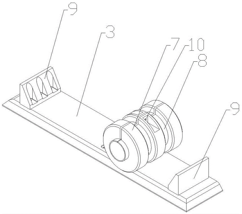
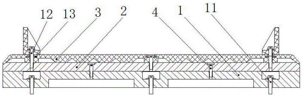
[0025] Such as figure 2 As shown, the high-voltage cable protection device at the train end of the EMU includes a base, which is a multi-layer structure, including a support base 1, a rubber cage 2 and a rubber pad 3 from bottom to top. The rubber cage 2 is fixed on the support base 1 by mounting screws 4, and the rubber pad 3 is mounted on the rubber cage 2 by bolts.

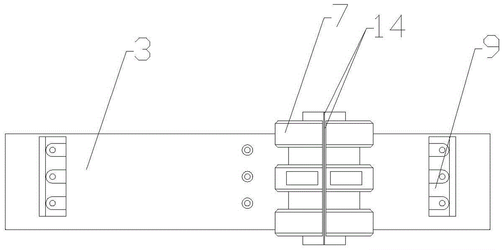
[0026] It also includes a sheath, which is lapped on the rubber pad 3 and can slide laterally along the rubber pad 3; the center of the sheath structure has a hollow hole running through the length direction of the sheath. The sheath has a multi-layer structure, from near the hollow to the outside of the hollow, sequentially including elastic rubber layer 5, steel ring layer 6 and wear-resistant rubber layer 7, elastic rubber layer 5, steel ring layer 6 and wear-resistant rubber layer 7 Each has an opening 14 running through its length, the wear-resistant rubber layer 7 has a groove 701 and a protrusion 702, ...

Embodiment 2

[0032] An EMU, equipped with a high-voltage cable protection device at the end of the EMU.

[0033] Two sets of protective devices are used in pairs and installed on two adjacent vehicles respectively. Such as figure 2 As shown, the support base is installed on the top of the adjacent place of the two vehicles by base mounting screws 11. The high-voltage cables pass through the hollow holes of the two roof sheaths in turn, and are connected to the electrical components in the car. The high-voltage cable passes through the protection device to a section connected to the electrical device in the car, and is fixed between the fixing parts installed at intervals and the roof of the car.

[0034] Since the length of the high-voltage cables at the train end of the EMU is carefully calculated, it will not be designed too long. Therefore, the high-voltage cables will not leave too much movement margin. Therefore, during the movement of the EMU, the high-voltage cables only Lateral...


PUM


Abstract

The invention discloses a protection device for a high-voltage cable at a train end of a motor train unit. The protection device is arranged at the top end of a roof at the adjacent place of two trains and is used for protecting the high-voltage cable. The protection device comprises a base and further comprises a sheath which is lapped on the base and can slide along the base transversely; the structure of the sheath forms a hollow hole penetrating through the length direction of the sheath; and stop blocks are arranged on the two transverse ends of the base. The protection device simultaneously solves the problems of stretch, bending and wear of the high-voltage cable of the motor train unit at the train end, the safety and the stability for train operation can be effectively improved, the problems of stretch and folding of the high-voltage cable at the train end due to train body swing and train turning are avoided, and the problems of wear and stripping of the protection sheath of the high-voltage cable due to mutual friction of the high-voltage cable at the train end and the train body are avoided.

Description

technical field [0001] The invention belongs to the technical field of rail transit equipment, and relates to a car-end high-voltage cable protection device applied to an EMU and an EMU. Background technique [0002] The high-voltage cable of the EMU is responsible for transmitting the power received by the pantograph to each power car. The safety of the high-voltage cable is crucial to the safe and stable operation of the vehicle. [0003] The high-voltage cables are located on the roof, and the relative movement between the cables and the roof during the train operation is likely to cause wear and tear on the high-voltage cables. In addition, at the end of the vehicle, due to the swing of the vehicle body and the turning of the vehicle, the straight-line distance between the two vehicles changes, and the high-voltage cables are often stretched or bent, which aggravates the wear and tear of the high-voltage cable protective skin, causing dangerous accidents such as leakage....

Claims


Application Information

Patent Timeline
Patent Type & Authority Applications(China)
IPC IPC(8): H02G3/04B61C17/00
CPCH02G3/04B61C17/00
Inventor 李刚张守春陆开元赵希远李作鑫
Owner CRRC QINGDAO SIFANG ROLLING STOCK RES INST
Why Eureka
Try Eureka