Collision energy-dissipation spacing rod

A technology of spacers and metal hollow spheres is applied in the installation of devices, electrical components, and cables that maintain the distance between parallel conductors. Well-designed effects

Active Publication Date: 2016-05-04
DALIAN UNIV OF TECH
View PDF7 Cites 7 Cited by
  • Summary
  • Abstract
  • Description
  • Claims
  • Application Information

AI Technical Summary

Problems solved by technology

At present, our country mainly realizes the purpose of suppressing the vibration of the wire by install

Method used


Image

  • Collision energy-dissipation spacing rod
  • Collision energy-dissipation spacing rod

Examples


Example Embodiment

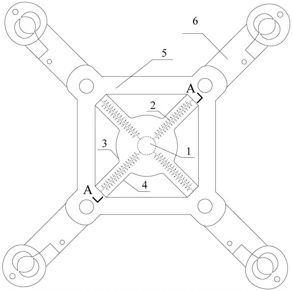
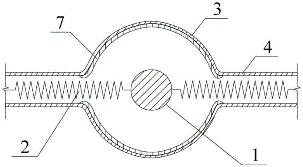
[0010] Such as figure 1 , figure 2 A collision energy-consuming spacer is shown, which consists of a mass ball 1, a spring 2, a metal hollow ball 3, a metal round tube 4, a spacer frame 5, a wire clamp 6 and a viscoelastic material layer 7.

[0011] The metal hollow sphere 3 is a hollow sphere structure, and the surrounding area is open at the connection with the metal round tube 4, and the joint with the metal round tube 4 is smoothed to prevent the spring 2 from jamming. The mass ball 1 and the viscoelastic material layer 7 are all located in the metal hollow ball 3: the mass ball 1 is suspended in the metal hollow ball 3, and the suspension point is located in the center of the metal hollow ball 3; the viscoelastic material layer 7 is attached The formula is set on the inner wall of the metal hollow ball 3, so as to absorb energy, consume energy and reduce vibration. The other end of the metal round tube 4 is fixedly connected with the spacer frame 5. The spring 2 is locate...


PUM


Abstract

The invention belongs to the technical field of vibration attenuation of electrical equipment and power transmission circuits, and relates to a collision energy-dissipation spacing rod. The collision energy-dissipation spacing rod is composed of a mass ball, a spring, a metal hollow ball, a metal circuit tube, a spacing rod frame, a wire clamp and a viscoelastic material layer. The invention aims to solve the problems of being single in function and limited in vibration attenuation effect in the existing spacing rod. When the external environment load is relatively low, the vibration attenuation effect is realized with the help of swinging of the mass ball; when the external environment load is relatively high, the swinging amplitude of the mass ball is increased; the mass ball is collided with a viscoelastic material on the inner wall of the metal hollow ball; the viscoelastic material can absorb a part of energy in the collision process, such that the energy dissipation effect is realized; because the mass ball can swing in a space in any direction and can be collided with the viscoelastic material on the inner wall of the metal hollow ball, the collision energy-dissipation spacing rod has the multi-dimensional vibration attenuation characteristics; and furthermore, the collision energy-dissipation spacing rod is simple to design and manufacture and can be widely applied in the technical field of vibration attenuation of electrical equipment and power transmission circuits.

Description

technical field [0001] The invention relates to the technical field of vibration reduction of power equipment and transmission lines, in particular to a collision energy-consuming spacer. Background technique [0002] As my country's demand for electricity increases, the span of transmission lines and the number of splits of conductors are all on the rise. The vibration of the transmission line under the wind load is very serious. According to the vibration frequency and amplitude of the conductor, it can be roughly divided into breeze vibration (high frequency and low amplitude), sub-gap vibration (medium frequency and medium amplitude) and galloping ( Low frequency high amplitude) 3 types. Vibration of transmission lines may cause hazards such as broken wires and strands due to fatigue, which greatly threatens the safe operation of transmission lines. In order to reduce the harm of conductor vibration to transmission lines, effective measures must be taken to suppress it...

Claims


Application Information

Patent Timeline
IPC IPC(8): H02G7/12H02G7/14
CPCH02G7/125
Inventor 李宏男付兴
Owner DALIAN UNIV OF TECH
Why Eureka
Try Eureka