Solar Electronic Switch

An electronic switch, solar energy technology, applied in electronic switches, circuits, electrical components, etc., can solve problems such as unfavorable normal operation of electronic products, inconvenience, etc., and achieve the effect of excellent mirror reflection performance

Active Publication Date: 2018-07-27
东莞市宇捷电子科技有限公司
View PDF3 Cites 0 Cited by
  • Summary
  • Abstract
  • Description
  • Claims
  • Application Information

AI Technical Summary

Problems solved by technology

[0002] The light control switch is a relatively common automatic control switch, which is usually kept on under the light condition, and kept off in the dark environment; the current light control switch generally uses a photosensitive diode, which is characterized in that it can be turned off quickly when there is light. This is extremely inconvenient for electronic products used for outdoor activities. In fact, for dynamic products, even in the sun, they may be damaged by themselves or the human body. The shadow is temporarily covered, in this case, if the switch is intermittent, it is not conducive to the normal operation of electronic products

Method used


Image

  • Solar Electronic Switch
  • Solar Electronic Switch

Examples


Embodiment 1

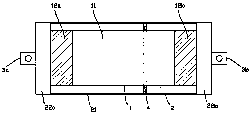
[0014] exist figure 1 In the first embodiment shown, the solar electronic switch includes a dark smooth heat-conducting cylinder 1, the central section of the heat-conducting cylinder 1 is an insulating column 11, and the two ends of the insulating column 11 are respectively connected to a short metal column 12a, 12b; the heat conduction column 1 is enclosed in an insulating sleeve 2, and each of the metal studs 12a, 12b is electrically connected to the terminals 3a, 3b at the ends of the insulating sleeve; and the insulating tube The coaxial side wall of the sleeve 2 and the heat conduction cylinder 1 is composed of a glass tube 21, and the inside of the glass tube 21 is evacuated; a space between the glass tube 21 and the heat conduction cylinder 1 is provided with a sleeve The annular sliding plug 4 on the heat conduction column 1; one side of the annular sliding plug 4 is sealed with mercury, and when the temperature is below 30°C, the volume of the mercury is not enough t...

Embodiment 2

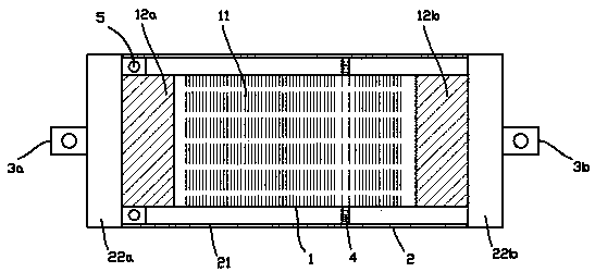
[0018] for figure 2 The second embodiment shown is different from the first embodiment in that an inductor is provided inside the insulating column 11 of the heat conducting column 1, and a photodiode 5 is also provided at one end of the glass tube 21. , the photodiode 5 and the inductor are connected in series between the two metal stubs 12a, 12b. According to this scheme, when the electronic switch receives light, the circuit can be connected immediately through the photodiode 5, and when the photodiode 5 is momentarily shaded, the circuit will not be disconnected immediately due to the buffer of the inductance. Therefore, as long as the electronic switch is turned on by sunlight, it will continue to irradiate to the metal short columns 12a, 12b at both ends of the mercury insulating column, so that it will not be afraid of short-term shading. That is to say, this solution enables the electronic switch to be turned on immediately after being exposed to sunlight, and will n...


PUM


Abstract

Provided in the invention is a solar electronic switch comprising a dark smooth heat-conducting cylinder. An insulating column is arranged at the central segment of the heat-conducting cylinder; and the two ends of the insulating column are connected with short metal columns respectively. The heat-conducting cylinder is enclosed into an insulating pipe casing. All short metal columns are connected with wiring posts arranged at the end portions of the insulating pipe casing electrically. The side wall of the insulating pipe casing is formed by a glass tube, wherein the side wall and the heat-conducting cylinder are in a coaxial mode; and the inside of the glass tube is processed by vacuumizing. Besides, an annular sliding plug sleeving the heat-conducting cylinder is arranged in the space between the glass tube and the heat-conducting cylinder; mercury is enclosed inside one side of the annular sliding plug; and an overlap joint with the short metal columns at the two ends of the insulating column can not be realized based on the size of the mercury at the temperature below 30 DEG C. The solar electronic switch can be connected all the time in a solar illumination environment and is not affected by instantaneous shielding; and the electronic product can work normally all the time during the continuous motion process.

Description

technical field [0001] The invention relates to the field of electronic switches, in particular to a light control switch. Background technique [0002] The light control switch is a relatively common automatic control switch, which is usually kept on under the light condition, and kept off in the dark environment; the current light control switch generally uses a photosensitive diode, which is characterized in that it can be turned off quickly when there is light. This is extremely inconvenient for electronic products used for outdoor activities. In fact, for dynamic products, even in the sun, they may be damaged by themselves or the human body. The shadow is covered instantly. In this case, if the switch is intermittent, it is not conducive to the normal operation of electronic products. Contents of the invention [0003] In view of the above problems, the object of the present invention is to provide a solar electronic switch, which can be kept on in the sunlight envir...

Claims


Application Information

Patent Timeline
Patent Type & Authority Patents(China)
IPC IPC(8): H03K17/94H03K17/74H03K17/78
Inventor 马根昌
Owner 东莞市宇捷电子科技有限公司
Why Eureka
Try Eureka