Mobile vehicle wireless charging device

A wireless charging and vehicle technology, applied in circuit devices, battery circuit devices, electric vehicles, etc., can solve the problems of inability to receive energy, low received energy, fluctuation, etc., and achieve the effect of saving manpower, small energy fluctuation, and convenient use

Pending Publication Date: 2018-11-13
北京动力京工科技有限公司
View PDF23 Cites 1 Cited by
  • Summary
  • Abstract
  • Description
  • Claims
  • Application Information

AI Technical Summary

Problems solved by technology

But in the same way, when the receiving coil is connected between two adjacent transmitting coils, due to the cancellation of the magnetic field, the energy cannot be received
Therefore, it is necessary to detect the position of the receiving coil to close a transmitting coil. This control is more complicated, and the detection of the position of the receiving coil also increases the cost of the system, and the received energy will fluctuate relatively large, or even fluctuate to zero.
[0005] Chinese patent CN201510291779.1 discloses a road guardrail charging system and method for wireless mobile charging of electric vehicles. This invention changes the transmitting coil and receiving coil from the bottom of the electric vehicle to the side of the electric vehicle, which does not solve the problem of crossover transmission. The problem of receiving energy drop when the coil
At the same time, the side of the car is generally not the bright side, and the effect of installing the receiving coil on the curved arc surface will be more affected
[0006] Chinese patents CN201710189628.4, CN201710290892.7, CN201620747991.4, and CN201610438208.0 also disclose several wireless charging devices for mobile vehicles, but none of them propose a solution to the problem of receiving fluctuations in receiving coil energy during the movement process
At the same time, it is necessary to solve the problem that there is a state where the energy received at a certain position is very low.

Method used


Image

  • Mobile vehicle wireless charging device
  • Mobile vehicle wireless charging device
  • Mobile vehicle wireless charging device

Examples


Embodiment Construction

[0043] The present invention will be further introduced below in conjunction with the drawings.

[0044] One of the embodiments of the present invention: the wireless charging application of the electric vehicle 4 in the rotary stereo garage 1

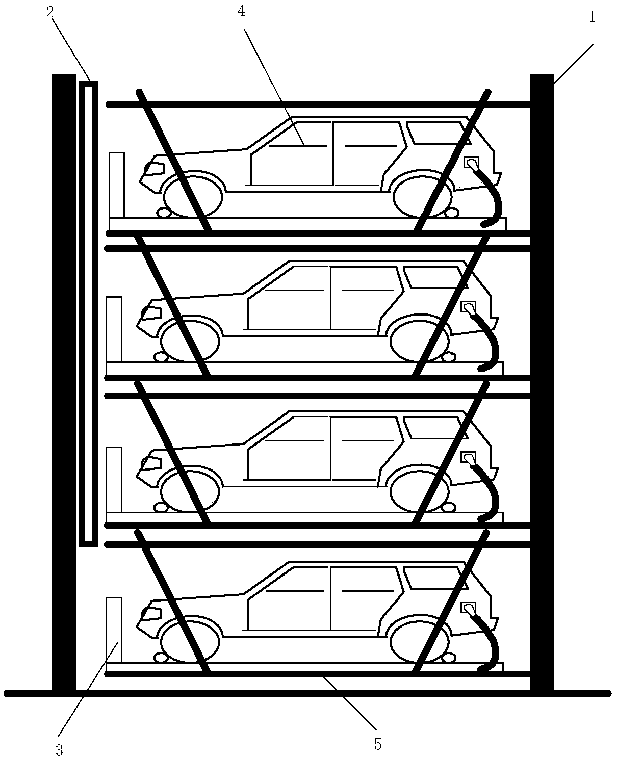
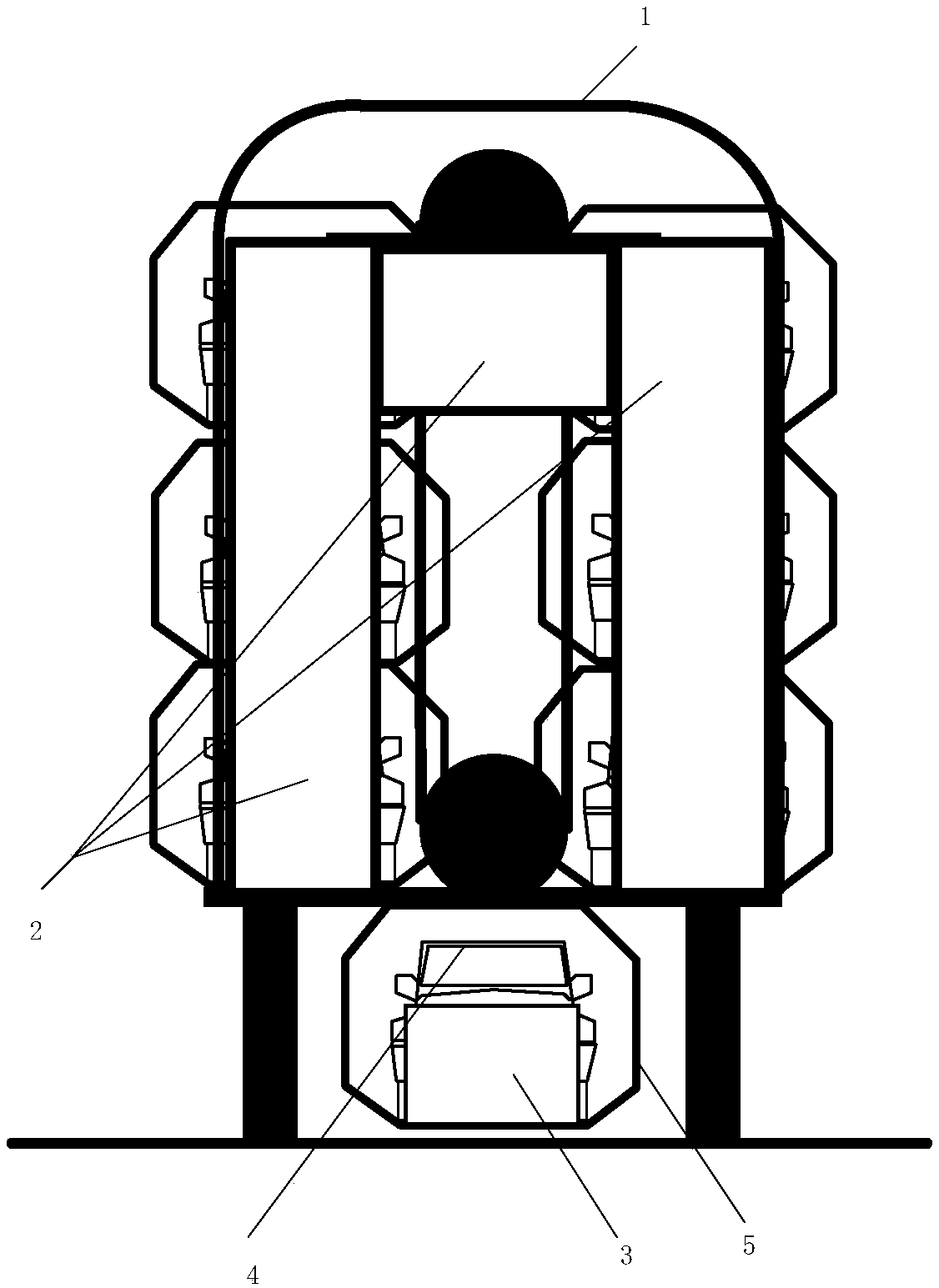
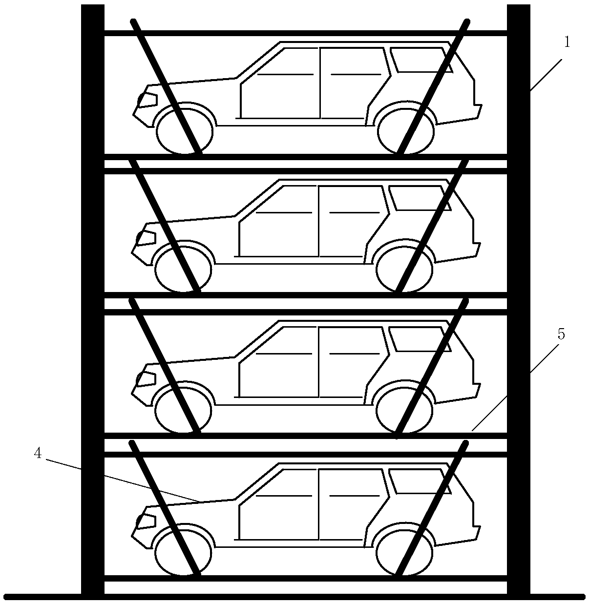
[0045] The traditional rotating three-dimensional garage such as image 3 with Figure 4 As shown, the suspension frame 5 is mechanically transmitted in the three-dimensional garage to drive each suspension frame 5 arranged in a vertical manner to make continuous circular rotation movement. Therefore, the traditional rotating stereo garage cannot charge the electric vehicle 4 in the garage. For this reason, the present invention discloses a charging device, which can enable the electric vehicle 4 in the rotating three-dimensional garage to be charged in real time during the moving process without intermittent situations.

[0046] This embodiment includes a rotary stereo garage 1, a wireless energy transmitting module 2, a wireless energy rec...


PUM


Abstract

The invention discloses a mobile vehicle wireless charging device. The mobile vehicle wireless charging device comprises a rotating type stereo garage, a wireless energy transmitting module, wirelessenergy receiving modules, an electric vehicle and suspension frames; the wireless energy receiving modules are mounted on the suspension frames; the wireless energy transmitting module is mounted on afixing bracket of the rotating type stereo garage and right against the suspension frames so that the wireless energy transmitting module can transmit energy to all wireless energy receiving modulesin moving. According to the mobile vehicle wireless charging device, multiple transmission coils are continuously arranged on an electric vehicle moving path and can continuously transmit energy to electric vehicles; during wireless charging, the electric vehicles can move on roads in the horizontal direction and can also move in the stereo garage in the vertical direction; when the electric vehicles move in each direction, the wireless charging device can continuously provide electric energy for the electric vehicles in real time without any contact, and the received energy fluctuation is very small; and the application range of the wireless charging can be effectively enlarged, and the use effect of the wireless charging can be effectively improved.

Description

Technical field [0001] The invention relates to a mobile vehicle wireless charging device, which belongs to the field of wireless energy transmission in electric vehicle applications. Background technique [0002] The rapid development of electric vehicles in our country, especially large cities began to restrict fuel vehicles, so the application of electric vehicles is becoming more and more extensive, but the biggest problem of electric vehicles is that the storage energy of the battery is limited and the charging time is long. These two shortcomings greatly limit Application range of electric vehicles. For this reason, electric vehicles need to be charged anytime and anywhere as much as possible. However, the number of parking lots in big cities has a large gap compared with the huge number of vehicles. The fixed parking spaces on the ground are very limited, so the construction of three-dimensional parking garages is very necessary. At present, most of the three-dimensional...

Claims


Application Information

Patent Timeline
Patent Type & Authority Applications(China)
IPC IPC(8): B60L11/18H02J7/02H02J50/10
CPCH02J7/025H02J50/10
Inventor 冬雷郝颖林达王晓晓
Owner 北京动力京工科技有限公司
Why Eureka
Try Eureka