
Radioactive waste plasma gasification melting furnace of dumping type molten pool

A radioactive waste and plasma technology, applied in the fields of radioactive purification, melting, chemical/physical/physical-chemical processes of applying energy, etc., can solve the problems of increasing the amount of post-processing waste disposal, high plasma torch energy, and high sealing difficulty, Achieve the effect of reducing energy fluctuations in the furnace, improving heat and mass transfer, and facilitating installation and maintenance.

Active Publication Date: 2022-05-06
JIANGSU TIANYING PLASMA TECH CO LTD +2
View PDF7 Cites 0 Cited by
  • Summary
  • Abstract
  • Description
  • Claims
  • Application Information

AI Technical Summary

Problems solved by technology

[0003] Traditional radioactive waste heat treatment technology adopts pyrolysis incineration technology, but pyrolysis incineration technology cannot handle non-combustible waste and low calorific value waste well, so plasma gas The chemical melting technology has been applied and promoted abroad because of its ability to process non-combustible waste, product vitrification, and nuclide solidification stability.
Such as CN111473339A "an improved pyrolysis incinerator for combustible radioactive waste", the shortcoming of this patent is that the waste after incineration and pyrolysis is discharged in the form of ash and needs to be further solidified, and the pyrolysis incinerator has dynamic functions such as stirring and double-layer grate. The structure increases the amount of waste disposal after treatment
The existing plasma gasification and melting radioactive waste treatment technology is mainly based on the shaft furnace. In the actual application process, there are problems such as uneven heating of the molten pool, deposition of metal bottom, and easy blockage of the slag discharge channel.
Such as CN110121750A "radioactive waste treatment device", the disadvantage of this patent is that the distance between the plasma torch and the bottom of the shaft furnace is relatively long, the bottom of the molten pool is unevenly heated, and cold slag is likely to appear, and the refractory material directly below the torch is easily corroded by high temperature. The way of slag is side discharge, and the molten and deposited metal cannot be completely discharged
Such as CN102859280B "tilting furnace", the disadvantage of this patent is that the energy of the plasma torch is too high, the requirements for refractory materials are very high, the gasification and melting furnace cannot establish a material layer buffer, and the low boiling point nuclides volatilize a lot; the working conditions fluctuate when feeding materials Larger, it is difficult to maintain stable operation of the combustion chamber and exhaust gas purification system; there are moving mechanisms in the feed and exhaust gas, and the sealing is difficult

Method used


Image

  • Radioactive waste plasma gasification melting furnace of dumping type molten pool
  • Radioactive waste plasma gasification melting furnace of dumping type molten pool

Examples


Embodiment Construction

[0024] In order to explain in detail the technical solutions adopted by the present invention to achieve the intended technical purpose, the technical solutions in the embodiments of the present invention will be clearly and completely described below in conjunction with the drawings in the embodiments of the present invention. Obviously, the described implementation Examples are only part of the embodiments of the present invention, rather than all embodiments, and, on the premise of not paying creative work, the technical means or technical features in the embodiments of the present invention can be replaced, the following will refer to the accompanying drawings and combine Examples illustrate the present invention in detail.

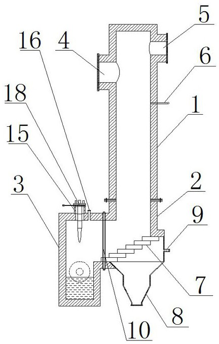
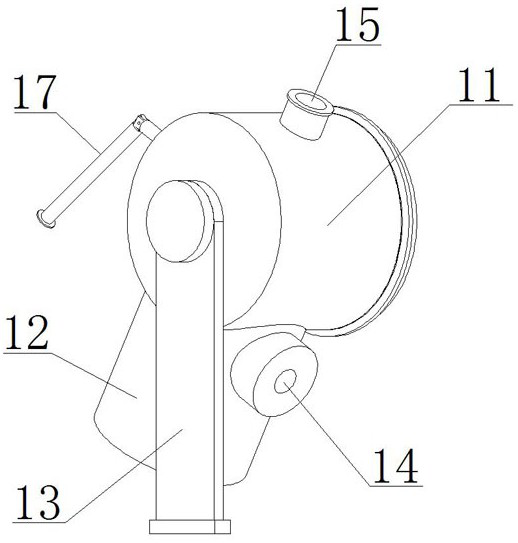
[0025] Such as figure 1 As shown, a radioactive waste plasma gasification and melting furnace of a pouring molten pool of the present invention comprises a shaft furnace drying and pyrolysis section 1, a furnace exhaust gasification oxidation section ...


PUM


Abstract

The invention discloses a radioactive waste plasma gasification melting furnace of a dumping type molten pool, which comprises a shaft furnace drying pyrolysis section, a furnace gas gasification oxidation section and a molten pool melting section, and the lower end of the shaft furnace drying pyrolysis section is connected with the upper end of the furnace gas gasification oxidation section; the molten pool melting section is arranged on one side of the furnace gas gasification and oxidation section and rotationally connected with the furnace gas gasification and oxidation section. According to the plasma gasification melting furnace, the structural advantages of the shaft furnace, the grate furnace and the dumping furnace are combined, the molten pool is heated more evenly, the heating efficiency is higher, and deslagging is smoother.

Description

technical field [0001] The invention relates to a plasma gasification melting furnace, in particular to a plasma gasification melting furnace for radioactive waste in a pouring molten pool, and belongs to the technical field of gasification melting furnaces. Background technique [0002] With the development of nuclear technology, especially the nuclear power industry, low-level radioactive pollutants related to nuclear power production are inevitably produced, mainly waste generated during the production process, including process waste, pollutants during operation and maintenance, and process waste mainly includes Waste ion exchange values, filter sludge, waste filter elements, etc. During the overhaul process, there are discarded equipment, tools and materials, as well as discarded work clothes, gloves, paper and wiping materials contaminated by radioactivity. The main components of combustible solid waste are similar to those of domestic garbage and medical waste, but t...

Claims


Application Information

Patent Timeline
Patent Type & Authority Applications(China)
IPC IPC(8): B01J6/00B01J19/08G21F9/30
CPCB01J6/005B01J19/08G21F9/308Y02E20/12
Inventor 严圣军李要建杨华韩豪杰曹建涛邹晓鹏张为峰
Owner JIANGSU TIANYING PLASMA TECH CO LTD
Learn More