Ventilated device for ink transportation mechanism

A technology of ink feeding and ventilator, which is applied to printing presses, rotary printing presses, general parts of printing machinery, etc., to achieve the effect of saving time-consuming matching

Active Publication Date: 2016-05-11
MAN ROLAND MASCHINEN AG
View PDF8 Cites 1 Cited by
  • Summary
  • Abstract
  • Description
  • Claims
  • Application Information

AI Technical Summary

Problems solved by technology

The filter element of the ventilator upstream of the blowing and suction unit also prevents damage caused by contamination of the ventilator during operation

Method used


Image

  • Ventilated device for ink transportation mechanism
  • Ventilated device for ink transportation mechanism
  • Ventilated device for ink transportation mechanism

Examples


Embodiment Construction

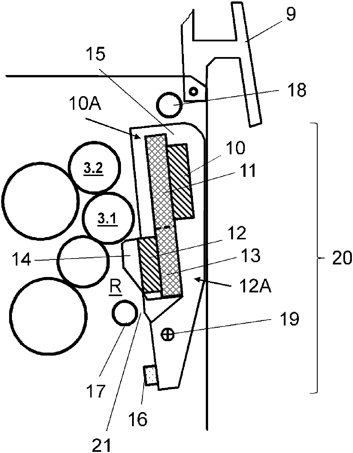
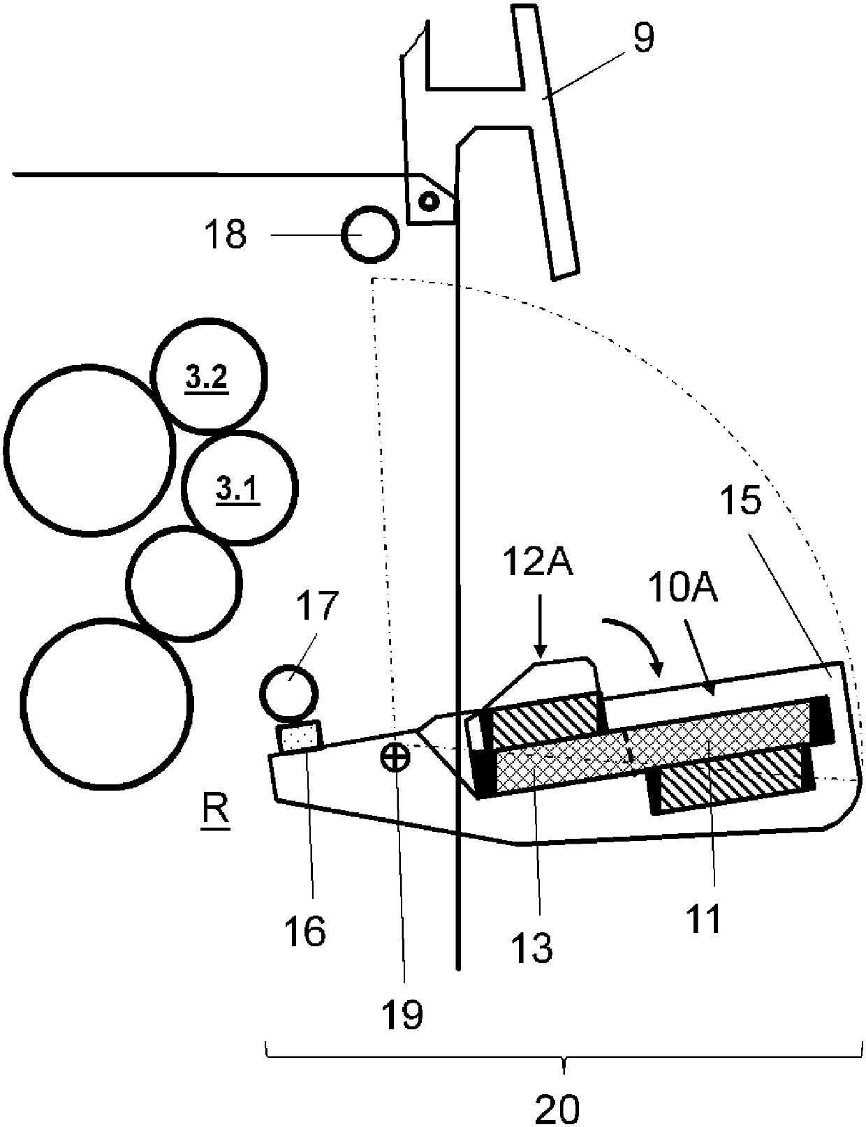
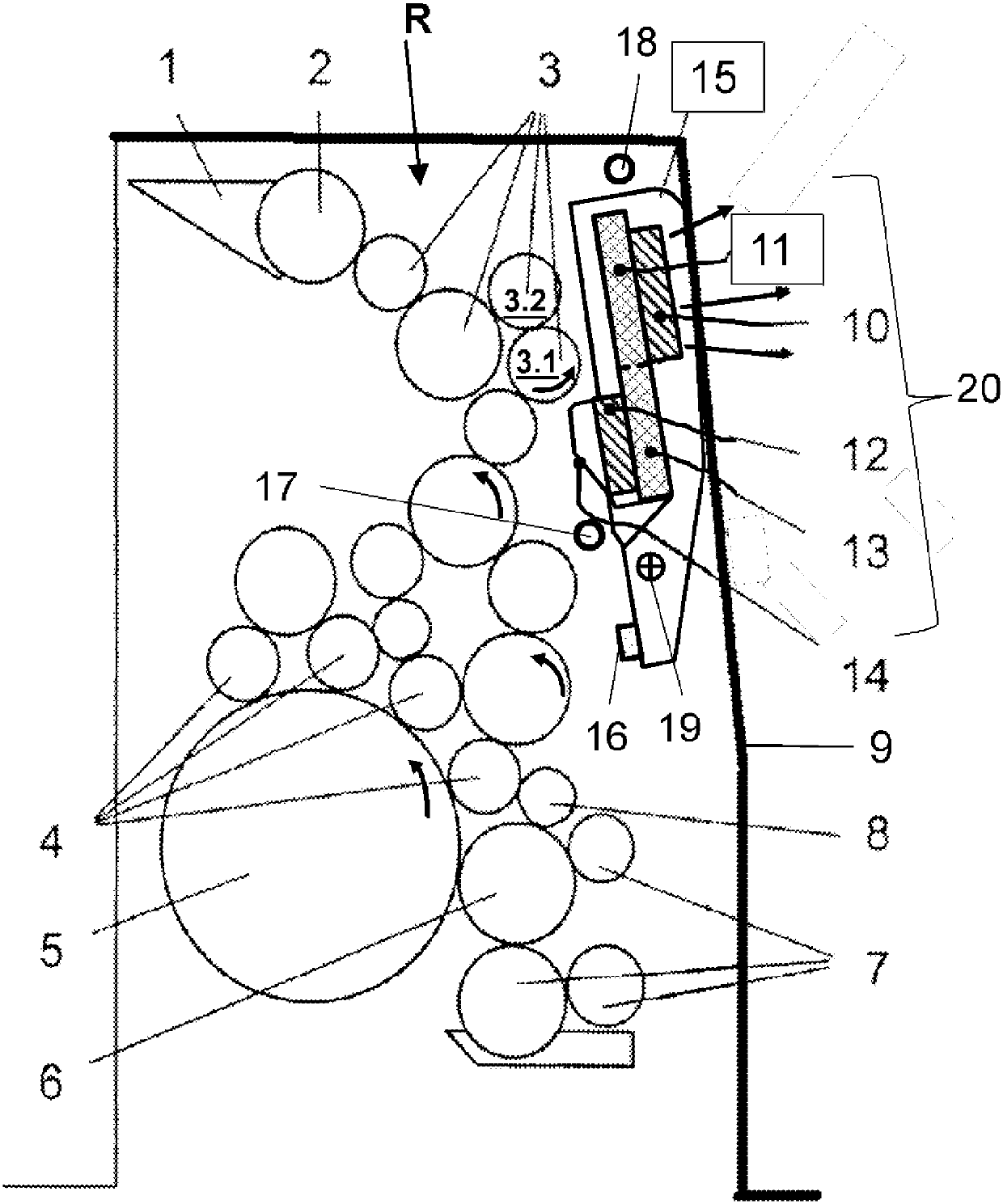
[0051] figure 1In the inking unit space R, an inking unit with a suction device 10A is shown. From the fountain 1 , the ink to be printed is applied via the fountain roller 2 , the inking unit roller 3 arranged downstream of the fountain roller 2 , and via the inking roller 4 onto the printing form stretched onto the plate cylinder 5 . A dampening applicator roller 6 is arranged upstream of the inking roller 4 in the direction of rotation of the plate cylinder 5 (counterclockwise). The dampening applicator roller 6 cooperates with the dampening roller 7 of the dampening mechanism. The wet applicator roller 6 is connected to the first inking roller 4 of the inking unit via a bridge roller 8 . The inking unit rollers 3 of the inking unit are covered by a displaceable, pivotable and pivotable printing unit guard 9 from the side of the feeder, not shown. A row of axial fans 10 is arranged on the printing unit guard 9 extending over the dimension width of the printing press, by ...


PUM


Abstract

The invention relates to a ventilated device for an ink transportation mechanism, and especially to an ink transportation mechanism sucking system for a paper feed printer provided with at least a ventilator before the ink transportation mechanism. Through the ventilator the air can be transported out from a ink transportation mechanism space (R). A filter element is arranged before the ventilator. The ventilator (10) of the sucking device (10A) is associated with an ink transportation mechanism blowing device (12A) which generates an air flow in the ink transportation mechanism. The ink transportation mechanism blowing device (12A) and the sucking device (10A), used as structure units, are associated with an upper region of the ink transportation mechanism and associated in a printing mechanism protection member (9) of a printing mechanism containing the ink transportation mechanism, wherein the structure units can be asway fixed at a printing mechanism rack.

Description

technical field [0001] The invention relates to a device for ventilation of an inking unit according to the preamble of claim 1 . Background technique [0002] In a feed offset press (Bogenoffsetdruckmaschinen, sometimes called a sheet-fed offset press), the ink to be printed is drawn from the ink fountain (Farbkasten), the ink fountain roller that cooperates with the ink fountain, the inking mechanism roller arranged behind, and the inking roller (Farbauftragwalze ) is applied to the printing plate tensioned on the Formzylinder. The large number of gap locations between the ten individual inking unit rollers is used to generate the necessary layer thickness for the ink applied to the printing plate. Depending on the type and nature of the printing ink, ink mist or ink splashes occur in each gap between the two inking unit rollers, which contaminate the surrounding machine parts, dry out and can therefore only be used with high-efficiency treatments Expends to clean up. ...

Claims


Application Information

Patent Timeline
Patent Type & Authority Applications(China)
IPC IPC(8): B41F31/00
CPCB41F22/00B41F13/42B41F31/001
Inventor H-B.耶格J.舍尔齐希
Owner MAN ROLAND MASCHINEN AG
Why Eureka
Try Eureka