Polar coordinate edge coding method based on circular model

A technology of edge coding and polar coordinates, applied in the field of edge coding of edge contour maps, can solve problems such as redundancy, large information, and low sensitivity

Inactive Publication Date: 2019-05-21
HARBIN UNIV OF SCI & TECH
View PDF5 Cites 5 Cited by
  • Summary
  • Abstract
  • Description
  • Claims
  • Application Information

AI Technical Summary

Problems solved by technology

[0003] The purpose of the present invention is to solve the problem that the commonly used Freeman edge chain code has relatively large information redundancy in simple graphic representation and low sensitivity in edge point detection and edge matching, and provides a polar coordinate edge based on the circle model. encoding method

Method used


Image

  • Polar coordinate edge coding method based on circular model
  • Polar coordinate edge coding method based on circular model
  • Polar coordinate edge coding method based on circular model

Examples


specific Embodiment approach 1

[0078] Specific embodiment one: a kind of polar coordinate edge coding method based on the circle model described in this embodiment includes the following steps:

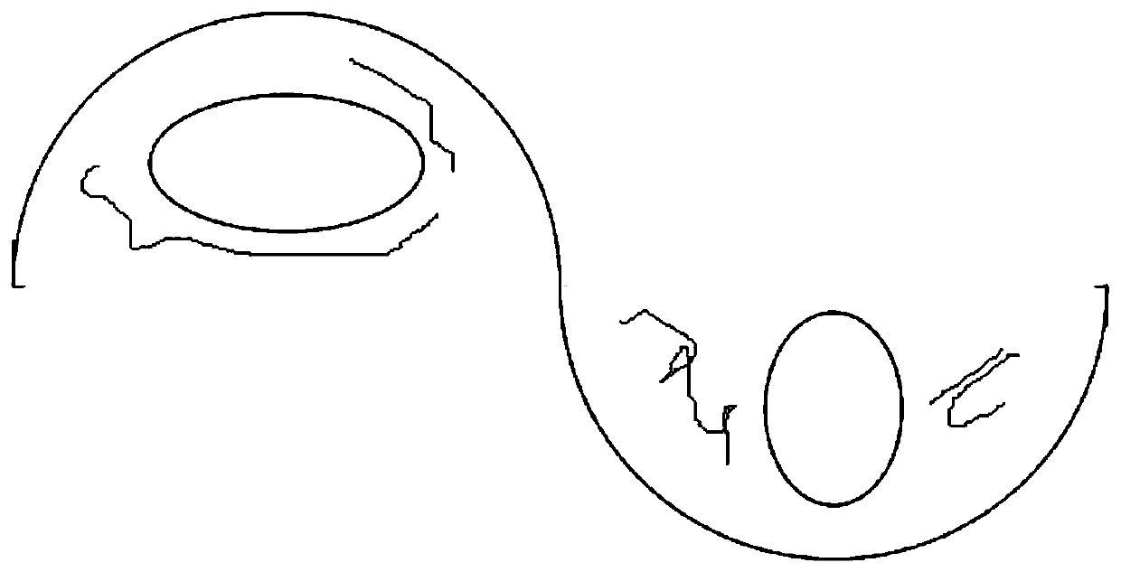
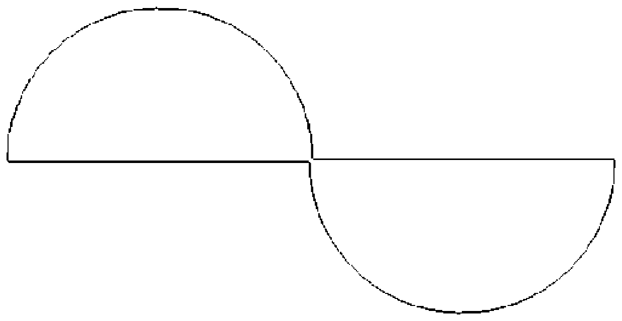
[0079] Step 1. Convert the image into a high-quality edge contour map. Since edge coding only requires the edge information of the image, it is necessary to de-content the image, and the quality of the edge contour image has an impact on the final coding result, so extract high The high-precision edge contour map is necessary. When obtaining the high-precision edge contour map in this embodiment, firstly, the preliminary edge contour map is obtained by conventional methods, and then the LOG operator and edge fitting are used to complete the acquisition of the high-precision edge contour map; then Solve the farthest distance D(o) between two points on the border of the edge contour map, and find the coordinates of the center point o of the line segment,

[0080] D(o)=max(||(x i -x j ),(y i -y j )|| 2 )

[0081...

specific Embodiment approach 2

[0122] Specific embodiment 2: This embodiment is a further limitation of the polar coordinate edge coding method based on the circle model described in Embodiment 1. In this embodiment, the method also includes:

[0123] Step 6. Obtain the original code, carry out sequential differential differentiation on the original code, and then perform minimum principle normalization to obtain the normalized differential code corresponding to the original code, and then perform complement code calculation on the normalized differential code:

[0124] n-direction normalized differential code:

[0125] the s i =(a i+1 ) n -(a i ) n

[0126] n+1=0

[0127] the s n =(a 0 ) n -(a n ) n

[0128] n-complement code:

[0129]

[0130] Among them: (a i ) n is the original code value of the i-th point of the n-direction code, (s i ) o Be the code value of the i-th point of the normalized differential code, n is an even number;

[0131] Step 7. Establish the subcode space as the e...

specific Embodiment approach 3

[0146] Embodiment 3: This embodiment is a specific implementation of the method described in Embodiment 1 in MATLAB software.


PUM


Abstract

The invention discloses a polar coordinate edge coding method based on a circular model, and relates to an edge coding technology of an edge contour map. The invention aims to solve the problems thata common Freeman edge chain code has relatively large information redundancy on simple graphic representation and has relatively low sensitivity on edge point detection and edge matching. The method comprises the following steps: firstly, carrying out edge contour map conversion on an image to be coded, then establishing an object by taking the edge contour map as a model, establishing a circularmodel, respectively solving a truncation radius, a centering angle and a relative position of a point of an edge contour, respectively detecting the points to obtain coded points, and coding accordingto a coding principle. According to the method, a new coding model and dynamic direction and dynamic code length coding are adopted, so that the coding length is effectively shortened, the coding efficiency is improved, the coding error can be effectively reduced, and a simple graph boundary can be efficiently represented on the graph table complexity.

Description

technical field [0001] The invention belongs to the field of image edge processing, in particular to an edge coding method of an edge contour map. Background technique [0002] Image edge coding technology has great significance in image edge description, compression and matching. Image edge coding is a kind of image edge processing technology. At present, Freeman edge chain code is widely used in image edge coding, which is a boundary representation method that uses the coordinates of the starting point of the curve and the boundary direction to describe the curve or boundary. Commonly used Freeman chain codes include 4-connected chain codes and 8-connected chains. 8-connected chain codes are used relatively more; 8-connected chain codes represent a direction in the horizontal, vertical and two diagonal directions, and the code length of the odd direction is √2, and the code length of the even direction is 1; The chain code can use less data to express the edge information...

Claims


Application Information

Patent Timeline
Patent Type & Authority Applications(China)
IPC IPC(8): G06T7/13G06T3/40
Inventor 宋立新章亚书马帅安佳星孙东梓
Owner HARBIN UNIV OF SCI & TECH
Why Eureka
Try Eureka