
Pose trajectory estimation method based on image frame interpolation method

An image and pose technology, applied in the field of pose trajectory estimation based on the image interpolation method, can solve the problem of low recognition accuracy and achieve the effect of improving recognition accuracy, accuracy, and robustness

Active Publication Date: 2021-03-09
NANJING UNIV OF POSTS & TELECOMM
View PDF3 Cites 5 Cited by
  • Summary
  • Abstract
  • Description
  • Claims
  • Application Information

AI Technical Summary

Problems solved by technology

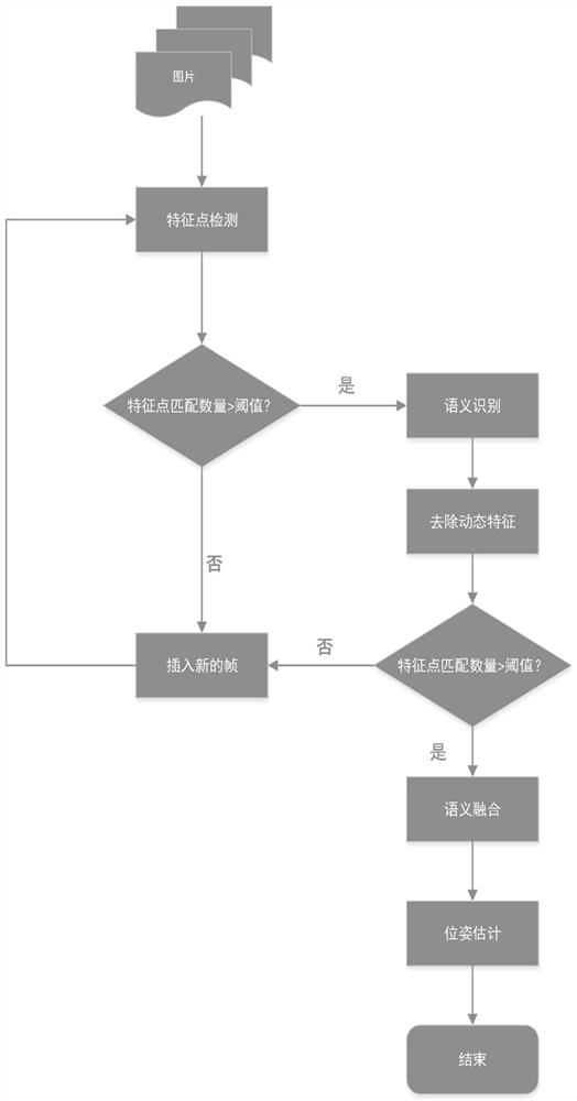
[0003] In order to overcome the deficiencies of the above-mentioned prior art, the present invention provides a pose trajectory estimation method based on the image interpolation method, which solves the problem in the prior art that the recognition accuracy of visual odometry for pose trajectory estimation based on captured images is not high

Method used


Image

  • Pose trajectory estimation method based on image frame interpolation method
  • Pose trajectory estimation method based on image frame interpolation method
  • Pose trajectory estimation method based on image frame interpolation method

Examples


Embodiment Construction

[0026] The specific implementation process of the present invention is described in detail below, and examples of the specific implementation process are shown in the drawings, wherein the same or similar reference numerals represent the same or similar elements or elements with the same or similar functions. The embodiments described below by referring to the figures are exemplary and are intended to explain the present invention and should not be construed as limiting the present invention.

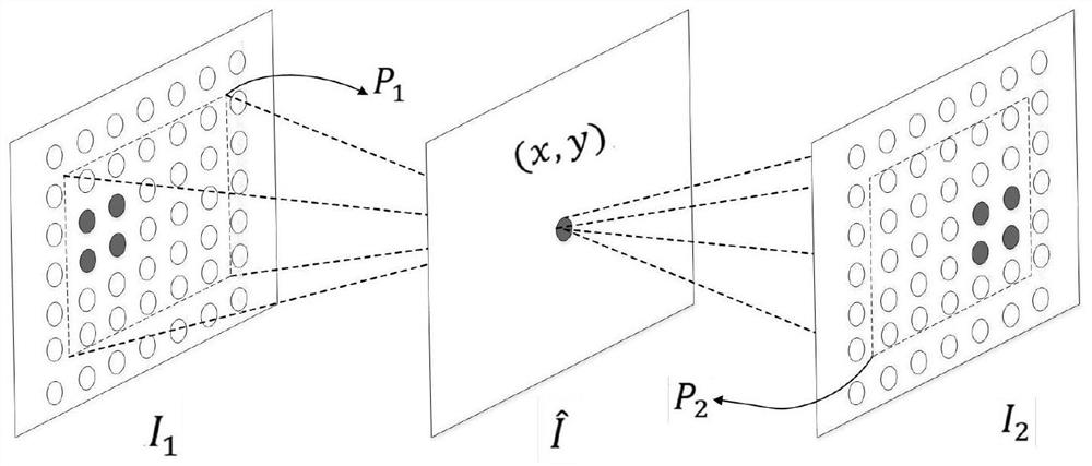
[0027] 1 image interpolation

[0028] When collecting images, it is inevitable that the camera moves too fast or the frame rate of the camera is too low, resulting in too little common view between two adjacent frames. Therefore, the use of video frame interpolation technology can effectively solve this problem.

[0029] As a preferred solution, a robust video frame interpolation method is used, which utilizes a deep convolutional neural network to achieve frame interpolation without ex...


PUM


Abstract

Provided is a pose trajectory estimation method based on an image frame interpolation method. A new frame is inserted between two image frames, semanteme is used as representation of an invariant scene, pose trajectory estimation is jointly restrained by the semanteme and feature points, the tracking loss situation is reduced by increasing the number of feature point matching between the frames, and the semantic information is fused to reduce the influence of dynamic object feature points and the matching of the constraint feature points, so that the accuracy of pose estimation and trajectoryestimation is improved. Experiments on a public data set show that the method maintains relatively high precision, is high in robustness for moving objects and sparse textures, and obtains a good result in the aspect of improving the recognition precision of the visual odometer.

Description

technical field [0001] The invention relates to the technical field of computer vision, in particular to a pose trajectory estimation method based on an image interpolation method. Background technique [0002] The goal of visual odometry is to estimate the motion of the camera based on the captured images. There are currently two commonly used methods, namely the feature point method and the direct method. Among them, the feature point method currently occupies the mainstream, and can achieve good results in places where the camera moves fast, the illumination changes are not obvious, and the environment is diverse. The result; the direct method does not need to extract features, but it is not suitable for the environment with fast camera movement. At the heart of visual odometry is the problem of data association, as it establishes pixel-level associations between images. These associated pixels are used to build a 3D map of the scene and track the current camera pose. ...

Claims


Application Information

Patent Timeline
Patent Type & Authority Applications(China)
IPC IPC(8): G06K9/62G06N3/04G06N3/08
CPCG06N3/08G06V10/751G06N3/045G06F18/25
Inventor 梁志伟郭强周鼎宇
Owner NANJING UNIV OF POSTS & TELECOMM
Learn More