High pressure injection system having fuel cooling from low pressure region

A high-pressure injection and fuel injection valve technology, which is applied to fuel injection devices, charging systems, engine components, etc., can solve problems such as increased fuel wear, high structural consumption, additional cost, and large engine space consumption. Design structure changes , to achieve a cost-effective effect

Inactive Publication Date: 2012-05-23
ROBERT BOSCH GMBH
View PDF6 Cites 11 Cited by
  • Summary
  • Abstract
  • Description
  • Claims
  • Application Information

AI Technical Summary

Problems solved by technology

This necessitates the use of correspondingly high-grade, expensive materials for the return line and leads to possible decomposition of the fuel and increased wear in the high-pressure injection system
[0004] A high-pressure injection system is known from KR-717316 B1 with a separate cooling device in the fuel return, however, this results in high structural outlay and corresponding additional costs and requires a relatively large amount of construction space due to its construction , which leads to the impossibility of implementing this solution at any position in the engine space or to a space-intensive design change of the engine

Method used


Image

  • High pressure injection system having fuel cooling from low pressure region
  • High pressure injection system having fuel cooling from low pressure region
  • High pressure injection system having fuel cooling from low pressure region

Examples


Embodiment Construction

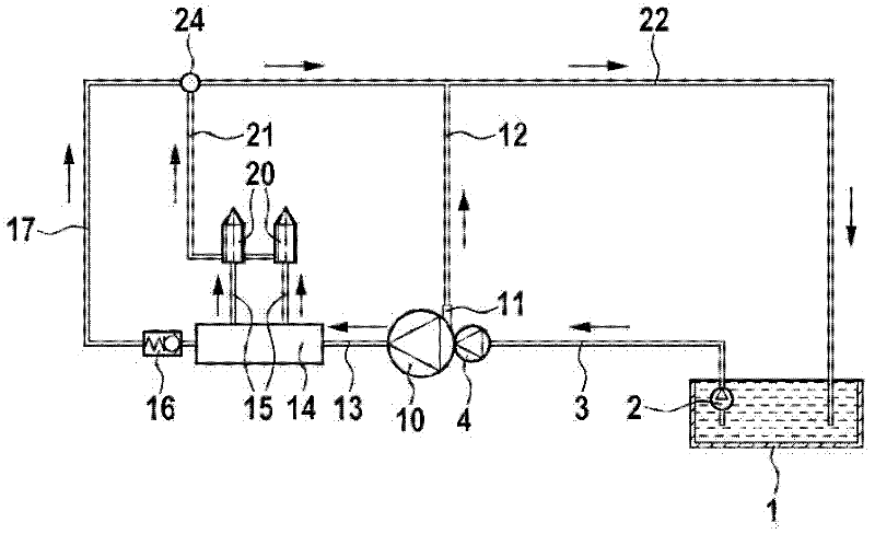
[0017] figure 1 A schematic diagram showing a high-pressure injection valve known from the prior art. The fuel is fed from the fuel tank 1 to the front-stage transfer pump 4 via the connecting pipe line 3 by means of the fuel transfer pump 2 and is fed to the high-pressure pump 10. The fuel tank 1, the fuel delivery pump 2, the connecting pipe 3, and the front delivery pump 4 are subjected to low pressure, and therefore are classified into the low pressure area.

[0018] A fuel return portion 11 is arranged on the high-pressure pump 10, and the fuel return portion 11 is connected to the fuel tank 1 via a return line 12 and another return line 22. In addition, the high-pressure pipe 13 passes from the high-pressure pump 10 to the high-pressure accumulator 14, the high-pressure accumulator 14 is also called a common rail, and the high-pressure accumulator 14 is connected to the fuel injection valve 20 via another high-pressure pipe 15. Here, the existing high-voltage storage 14 is...


PUM


Abstract

The invention relates to a high pressure injection system having a fuel tank, a connection line between the fuel tank and a high pressure pump for sealing the fuel, wherein the high pressure pump is connected to at least one fuel injection valve via a corresponding connection line. According to the invention, at least a partial volume of the fuel sealed in the high pressure pump is fed back to the fuel tank from said fuel injection valve by leakage in the fuel injection valve via a return line connected to the fuel tank. An essential characteristic of the invention is that the high pressure injection system comprises a cooling line that connects the fuel tank or the low pressure region to the high pressure or a return of the high pressure pump via a mixing point with the return line. It is thereby possible to cool the fuel in the return lines between the fuel injection valve and the fuel tank.

Description

Technical field [0001] The present invention relates to a high-pressure injection system, particularly used in a high-pressure-storage-injection system of an internal combustion engine, with a fuel tank from which the fuel is guided to the high-pressure pump through a fuel delivery pump and a pipeline system. The compression of the fuel is used in the high-pressure pump to increase the temperature of the fuel. The compressed fuel is guided by the high-pressure pump to a high-pressure accumulator through another pipeline, and the high-pressure accumulator itself is connected with at least one fuel injection valve. When the internal combustion engine is running, compressed fuel is injected from the fuel injection valve into the combustion chamber. A part of the fuel delivered to the fuel injection valve reaches the return line from the fuel injection valve through a leak in the fuel injection valve or as a controlled amount, wherein the leakage amount is reduced by reducing the a...

Claims


Application Information

Patent Timeline
Patent Type & Authority Applications(China)
IPC IPC(8): F02M53/00F02M55/00F02M63/02
CPCF02M55/002F02M63/0225F02M53/00
Inventor S·施平德勒J·瓦尔特D·佐默S·基费勒
Owner ROBERT BOSCH GMBH
Why Eureka
Try Eureka