Fool-proof control method and fool-proof control device

A control method and emergency braking technology, applied in the direction of automatic starting device, locomotive, etc., can solve the problem of not being able to remind the driver and so on.

Active Publication Date: 2016-05-11
CRRC DALIAN R & D CO LTD
View PDF8 Cites 2 Cited by
  • Summary
  • Abstract
  • Description
  • Claims
  • Application Information

AI Technical Summary

Problems solved by technology

[0005] The invention provides a fool-proof control method and device to solve the problem that the driver cannot be effectively reminded in the prior art

Method used


Image

  • Fool-proof control method and fool-proof control device
  • Fool-proof control method and fool-proof control device
  • Fool-proof control method and fool-proof control device

Examples


Embodiment Construction

[0032] In order to make the technical problems, technical solutions and advantages to be solved by the embodiments of the present invention clearer, the following will describe in detail with reference to the drawings and specific embodiments.

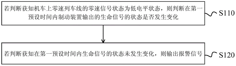
[0033] like figure 1 as shown, figure 1 It is a flow chart of the fool-proof control method provided by Embodiment 1 of the present invention. This fool-proof control method comprises the steps:

[0034] S110. If it is determined that the state of the zero-speed signal on the zero-speed train line on the locomotive is a low-level state, then determine whether the state of the life signal output by the braking device changes within the first preset time.

[0035] When the state of the zero-speed signal is a low level state, it can be considered that the locomotive is in a moving state, and the moving speed is greater than the set value; when the state of the zero-speed signal is a high level state, it can be considered that the locomo...


PUM


Abstract

The invention provides a fool-proof control method and a fool-proof control device. The fool-proof control method comprises the following steps: if the zero-speed signal state of a zero-speed train line on a locomotive is judged to be in a low-level state, judging whether the state of a life signal output by a brake device changes within the first preset time, and if the state of the life signal is judged to be unchanged within the first preset time, outputting an alarm signal. By the fool-proof control method, the problem that in the prior art, drivers cannot be effectively reminded is solved.

Description

technical field [0001] The invention relates to the technical field of locomotives, in particular to a foolproof control method and device. Background technique [0002] When the locomotive driver is driving, especially at night, it is very easy for the locomotive to lose consciousness or doze off and not concentrate. If the locomotive is running at a high speed at this time, it may be caused by the driver's inaction or wrong operation. Dangerous accidents such as inbound signals, exiting outbound signals, or overspeeding accidents. In order to avoid such accidents, the design of the locomotive usually requires the driver to operate the foot pedal or the level handle at regular intervals. Once the interval is not operated, emergency braking will be implemented. We call it foolproof control. . [0003] The existing fool-proof control is specifically: a timer is connected with the pedal or the level handle of the cab, and when the driver operates the pedal or the level handl...

Claims


Application Information

Patent Timeline
Patent Type & Authority Applications(China)
IPC IPC(8): B61C17/00B60T7/12
Inventor 矫德余赵国平吴涛石勇
Owner CRRC DALIAN R & D CO LTD
Why Eureka
Try Eureka