Pulse stick driving mechanism

A driving mechanism and pulse rod technology, which is applied in the field of pulse rod driving mechanism, can solve problems such as the inability to continue to increase the peak power of the stack, discontinuous pulse rod speed control, impact at the end of the mechanism, etc., to improve safety and reliability, vibration Small, highly reliable effect

Inactive Publication Date: 2014-12-17
SOUTHWEST JIAOTONG UNIV
View PDF5 Cites 2 Cited by
  • Summary
  • Abstract
  • Description
  • Claims
  • Application Information

AI Technical Summary

Problems solved by technology

Most of the pulse rod drive mechanisms currently in use use the impact cylinder as the drive element, which mainly has the following problems: (1) the firing speed is low, and the peak power of the stack cannot be continuously increased; (2) the impact and vibration at the end of the mechanism are large, Parts are easily damaged, and the failure rate is high; (3) The speed control of the pulse rod during launch is discontinuous, imprecise, and poor in repeatability

Method used


Image

  • Pulse stick driving mechanism
  • Pulse stick driving mechanism
  • Pulse stick driving mechanism

Examples


Embodiment

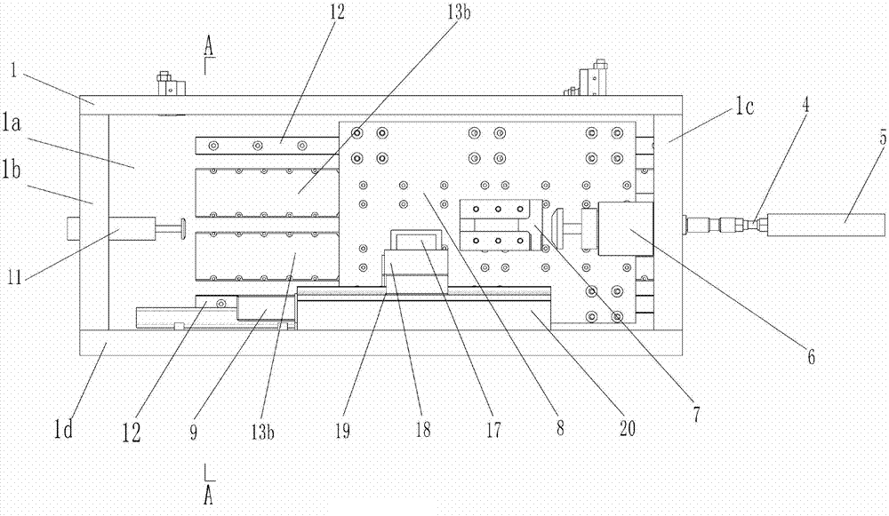
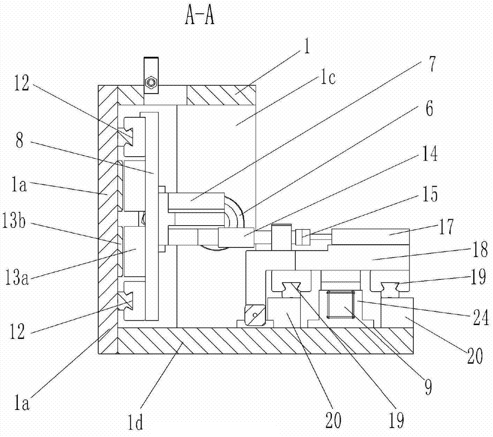
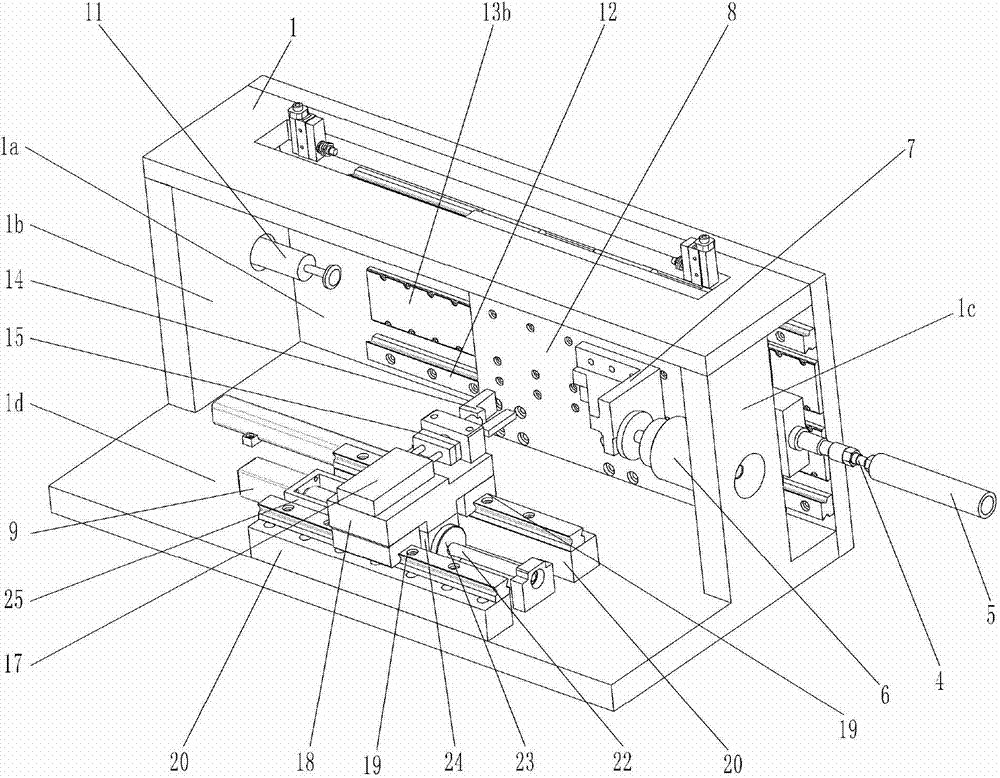
[0019] Figure 1-3 As shown, a specific implementation of the present invention is: a pulse rod drive mechanism, including a connecting rod 4 connected to the pulse rod 5, the connecting rod 4 is connected to the power mechanism, and is characterized in that:

[0020] The composition of described power mechanism is: the mover 13a of linear motor is fixed on the vertical slide table 8, and slide table 8 is connected with the side plate 1a of frame 1 by guide rail pair 12, and the stator 13b of linear motor is fixed on the side plate 1a; a front buffer 6 and a rear buffer 11 are respectively installed on the front plate 1c and the rear plate 1b of the frame 1, and the impact block 7 is installed on the slide table 8, and the front buffer 6 is aligned with the front part of the impact block 7, The rear bumper 11 is aligned with the rear of the slide table 8 .

[0021] A slow drive mechanism is also installed on the base plate 1d of the frame 1 of this example, the composition of...


PUM


Abstract

A pulse stick driving mechanism includes a connecting rod (4) which connects a pulse stick (5) and is connected to a power mechanism. The power mechanism is composed in a following manner: a rotor (13a) of a linear motor is fixed to a vertically-arranged sliding bench (8); the sliding bench (8) is connected to a side plate (1a) of a rack (1) through a guide rail pair (12); a stator (13b) of the linear motor is fixed to the side plate (1a); a front plate (1c) and a back plate (1b) of the rack (1) are respectively provided with a front buffer (6) and a back buffer (11); the sliding bench (8) is provided with an impacting block (7); and the front buffer (6) is aligned with a front part of the impacting block (7) and the back buffer (11) is aligned with a back part of the impacting block (7). By means of the driving mechanism, a launching speed can be increased. In addition, the pulse stick driving mechanism is less in impact and oscillation at an operating end and can achieve continuous and accurate control of the speed of a pulse stick.

Description

technical field [0001] The invention relates to a pulse rod driving mechanism of a nuclear reaction pulse reactor. Background technique [0002] The uranium hydrogen zirconium pulse reactor in the nuclear reactor is an advanced research reactor that can achieve instantaneous supercriticality and has high safety performance. It mainly uses hydrogen as a moderator. When the power increases, the temperature will increase, and the moderation effect of hydrogen will be weakened. , the reactivity decreases immediately, and the reactor has a large instantaneous negative temperature coefficient, so it operates in pulses. [0003] During the pulse reactor reaction, the neutron flux distribution in the pulse reactor is changed by inserting or withdrawing the pulse rod, thereby starting and stopping the pulse reactor reaction or changing the reaction power of the pulse reactor. Therefore, the pulse rod driving device is the key equipment of the pulse stack. Most of the pulse rod driv...

Claims


Application Information

Patent Timeline
Patent Type & Authority Applications(China)
IPC IPC(8): G21C7/14
CPCY02E30/30
Inventor 高宏力赵彬黄晓蓉范小强叶岑明张伟黄海凤许明恒
Owner SOUTHWEST JIAOTONG UNIV
Why Eureka
Try Eureka