Traction type elevator

A traction type and elevator technology, which is applied to elevators, lifts, transportation and packaging in buildings, etc., can solve the problems of poor safety control, poor safety control, and temperature rise in the mechanical room, and achieve speed reduction and safety control improvement. , the effect of simple control system

Inactive Publication Date: 2011-02-09
GUANGDONG HUANYU ELECTRONICS TECH CO LTD
View PDF4 Cites 2 Cited by
  • Summary
  • Abstract
  • Description
  • Claims
  • Application Information

AI Technical Summary

Problems solved by technology

[0003] 1. When the elevator is in a situation where the car is heavy and the counterweight is light and the car is going down or the car is light and the counterweight is heavy and the elevator is going up (hereinafter referred to as the elevator power generation state), the operation of the elevator will cause the power generation state of the control system. Additional circuits need to be added for processing, such as converting heat energy to be consumed, which will cause the temperature of the mechanical room to rise
[0004] 2. The structure must be able to realize the mechanical limit operation protection when the running speed of the car exceeds the rated running speed by a large proportion (for example, overspeed 130%, act as a mechanical safety gear, and limit the car or counterweight to the vertical position of the guide rail ), and require special treatment to operate normally, poor security control
[0005] 3. The braking device used by the elevator when it stops normally is the brake on the traction system. If the device is mechanically stuck, the elevator system can only realize overspeed detection and protection through the overspeed operation of the elevator. The elevator equipment has a great impact, and the safety control is poor

Method used


Image

  • Traction type elevator
  • Traction type elevator

Examples


Embodiment Construction

[0014] In order for those skilled in the art to further understand the features and technical content of the present invention, please refer to the following detailed description and accompanying drawings of the present invention.

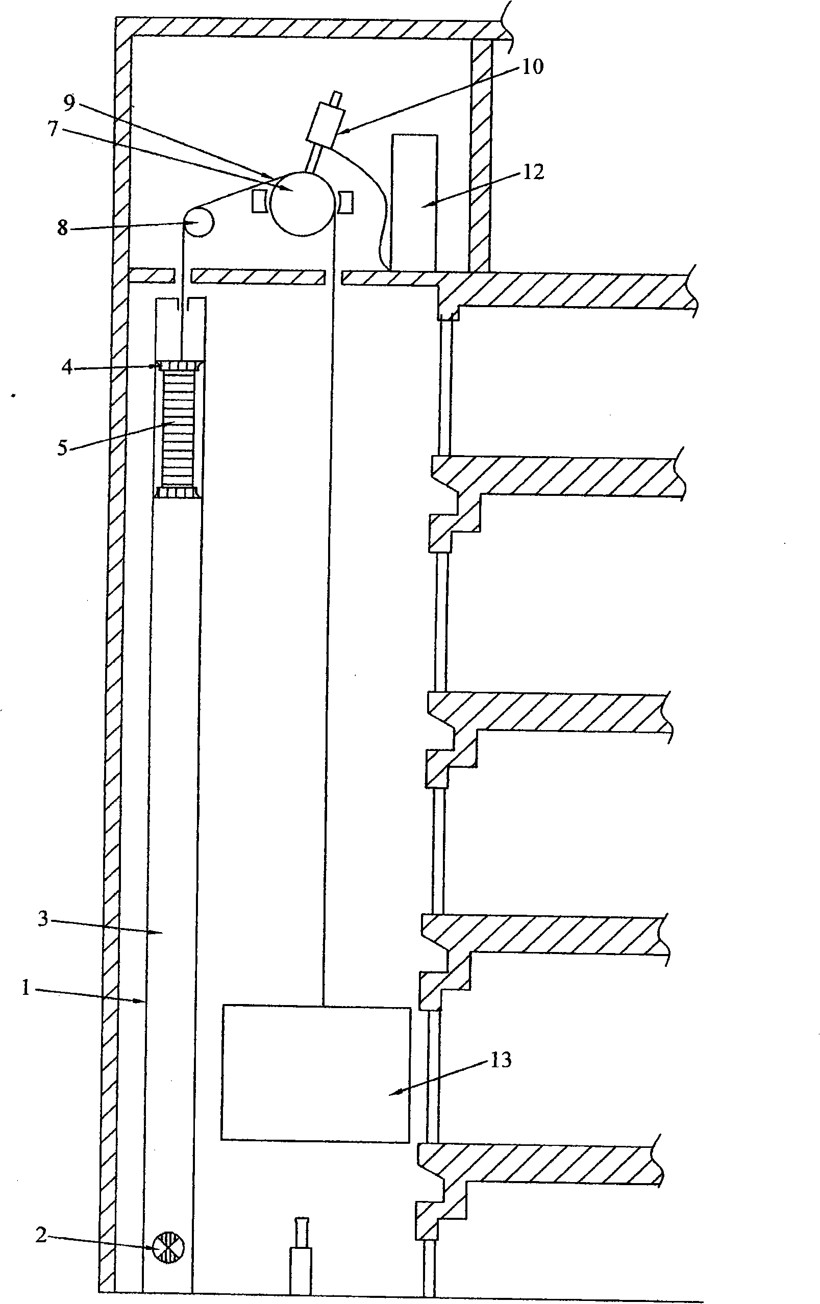
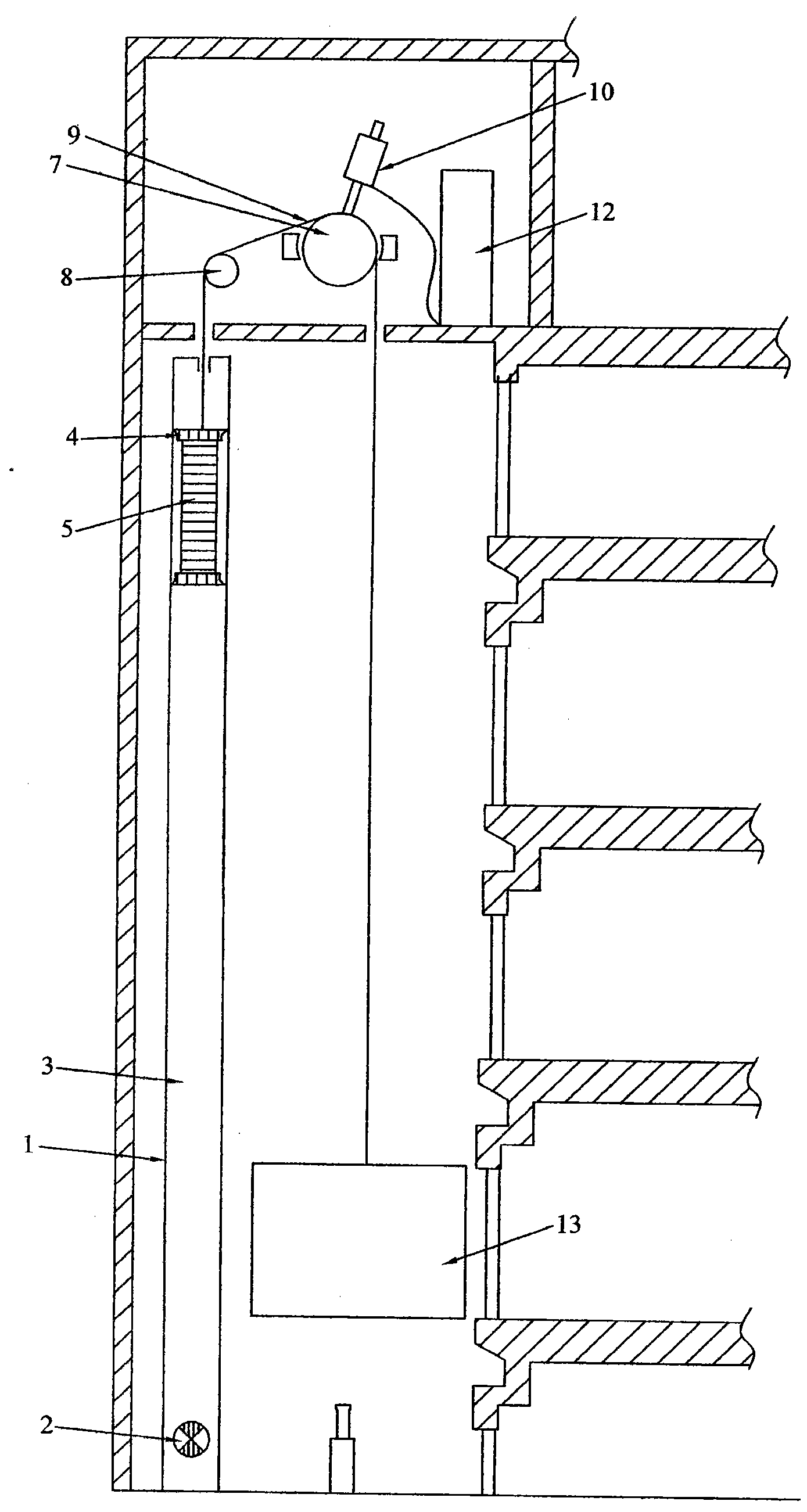
[0015] see figure 1 As shown, the present invention provides a traction elevator, including a traction guide device and a counterweight device and an elevator car 13 connected to both sides of the traction guide device, and the traction guide device is electrically connected to a motor 10 and a control device 12, wherein the counterweight device adopts a closed piston structure, and the closed piston structure includes a longitudinal piston cylinder 1, and a counterweight 5 is arranged in the piston cylinder 1, and the piston cylinder 1 has a piston movement space 3 for the counterweight 5 to move up and down. The counterweight 5 is provided with an air sealing device 4 that can closely contact the inner wall of the piston cylinder to achieve a sea...


PUM


Abstract

The invention relates to a traction type elevator which comprises a traction guiding device, a counterweight device and an elevator car, wherein the counterweight device and the elevator car are connected with the two sides of the traction guiding device; the traction guiding device is electrically connected with a motor and a control device; a sealed piston type structure is adopted by the counterweight device; the sealed piston type structure comprises a longitudinal piston barrel; a counterweight is arranged in the piston barrel; a piston motion space for the counterweight to move up and down is formed in the piston barrel; a hermetic sealing device which can be in close contact with the inner wall of the piston barrel to achieve the sealing effect is arranged on the counterweight; and a movable throttle of which the magnitude can be controlled by the control device is arranged in the position near the lower end of the piston barrel. The invention can better consume the extra energy generated by an elevator traction system in a generating state, and the safety performance is better.

Description

technical field [0001] The invention relates to an elevator device, in particular to a traction elevator. Background technique [0002] The dragging structure of a general traction elevator is composed of a car and a counterweight connected by a set of wire ropes suspended on both sides of the traction wheel and the guide wheel, and the relative fixing method of the car and the counterweight is respectively through Guide rails are installed on the hoistway walls to limit their movement tracks and brake in emergency situations. But this structure has the following disadvantages: [0003] 1. When the elevator is in a situation where the car is heavy and the counterweight is light and the car is going down or the car is light and the counterweight is heavy and the elevator is going up (hereinafter referred to as the elevator power generation state), the operation of the elevator will cause the power generation state of the control system. It is necessary to add additional cir...

Claims


Application Information

Patent Timeline
Patent Type & Authority Applications(China)
IPC IPC(8): B66B11/00B66B7/00
Inventor 黎振辉
Owner GUANGDONG HUANYU ELECTRONICS TECH CO LTD
Why Eureka
Try Eureka