Traction type elevator

A traction and elevator technology, which is applied to elevators, elevators in buildings, and lifting equipment in mines, etc., can solve problems such as temperature rise in mechanical rooms, poor safety control, and impact on passenger elevator equipment, and achieve a simple control system. , Security control improvement, to achieve the effect of multiple protection

Inactive Publication Date: 2019-05-21
郭媛媛
View PDF0 Cites 2 Cited by
  • Summary
  • Abstract
  • Description
  • Claims
  • Application Information

AI Technical Summary

Problems solved by technology

But this structure has the following defects: 1. When the elevator is in the situation that the car is heavy and the counterweight is light and the car is going down or the car is light and the counterweight is heavy and the elevator is going up (hereinafter referred to as the elevator power generation state), the operation of the elevator will cause The power generation status of the control system, the power needs to be processed by adding additional circuits, such as converting heat energy to be consumed, which will cause the temperature rise of the mechanical room
2. The structure must be able to realize the mechanical limit operation protection when the running speed of the car exceeds the rated running speed by a large proportion (for example, overspeed 130%, act as a mechanical safety gear, and limit the car or counterweight to the vertical position of the guide rail ), and require special treatment to operate normally, poor security control
3. The braking device used by the elevator when it stops normally is the brake on the traction system. If the device is mechanically stuck, the elevator system can only realize overspeed detection and protection through the overspeed operation of the elevator. The elevator equipment has a great impact, and the safety control is poor

Method used


Image

  • Traction type elevator

Examples


Embodiment Construction

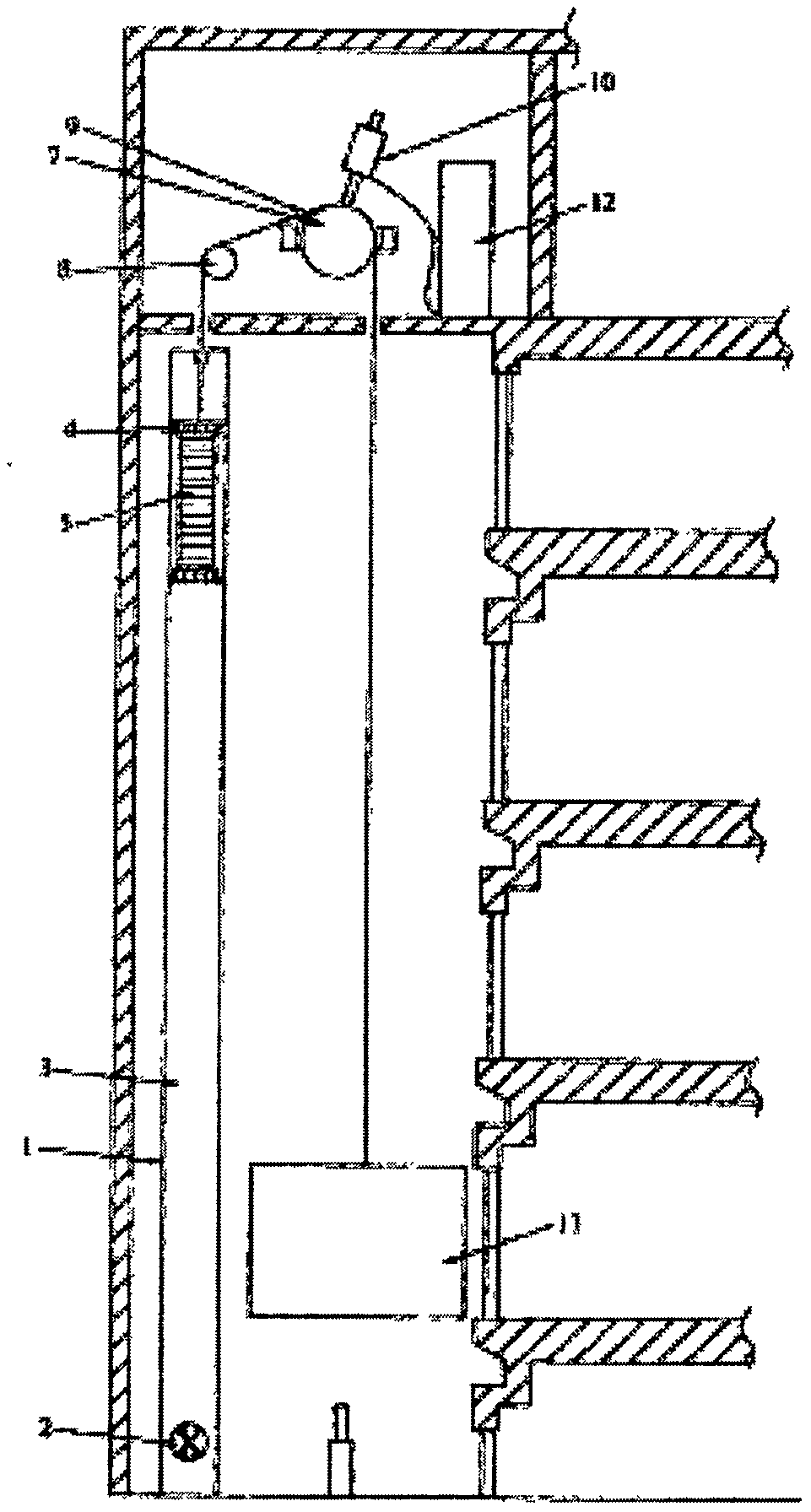
[0009] figure 1 As shown, the present invention provides a traction elevator, including a traction guide device and a counterweight device and an elevator car 13 connected to both sides of the traction guide device, and the traction guide device is electrically connected to a motor 10 and a control device 12, wherein the counterweight device adopts a closed piston structure, and the closed piston structure includes a longitudinal piston cylinder 1, and a counterweight 5 is arranged in the piston cylinder 1, and the piston cylinder 1 has a piston movement space 3 for the counterweight 5 to move up and down. The counterweight 5 is provided with an air sealing device 4 that can closely contact the inner wall of the piston cylinder to achieve a sealing effect. The lower end of the piston cylinder 1 A movable damper 2 capable of controlling the size of the damper through the control device 12 is provided at the position.


PUM


Abstract

The invention relates to a traction type elevator. The traction type elevator comprises a traction guide device as well as a counterweight device and an elevator car which are connected to the two sides of the traction guide device, wherein the traction guide device is electrically connected with a motor and a control device; the counterweight device adopts a sealed piston type structure which comprises a longitudinal piston barrel, wherein a counterweight is arranged in the piston barrel, a piston motion space for allowing the counterweight to move up and down is arranged in the piston barrel, a gas-sealing device which can be tightly in contact with the inner wall of the piston barrel to reach the sealing effect is arranged on the counterweight, and the position, close to the lower end,of the piston barrel is equipped with a movable air door capable of controlling the size of an air door through the control device. The traction type elevator can process extra energy generated when the traction type elevator is under a power generation state, and is better in safety performance.

Description

technical field [0001] The invention relates to an elevator device, in particular to a traction elevator. Background technique [0002] The dragging structure of a general traction elevator is composed of a car and a counterweight connected by a set of wire ropes suspended on both sides of the traction wheel and the guide wheel, and the relative fixing method of the car and the counterweight is respectively through Guide rails are installed on the walls of the hoistway to realize the limitation of their movement track and emergency braking. But this structure has the following defects: 1. When the elevator is in the situation that the car is heavy and the counterweight is light and the car is going down or the car is light and the counterweight is heavy and the elevator is going up (hereinafter referred to as the elevator power generation state), the operation of the elevator will cause The power generation status of the control system, the electric energy needs to be proce...

Claims


Application Information

Patent Timeline
Patent Type & Authority Applications(China)
IPC IPC(8): B66B9/04B66B11/04B66B17/12B66B1/30
Inventor 郭媛媛
Owner 郭媛媛
Why Eureka
Try Eureka