Weaving cage rebar storage rack used for pipe pile production line and weaving cage rebar conveying device

A technology of conveying device and storage rack, applied in the field of construction, can solve the problems of low degree of automation and low production efficiency, and achieve the effect of improving the degree of automation

Active Publication Date: 2016-05-11
浙江兆弟技术有限公司
View PDF8 Cites 6 Cited by
  • Summary
  • Abstract
  • Description
  • Claims
  • Application Information

AI Technical Summary

Problems solved by technology

[0014] The above-mentioned skeleton production is the production of steel cages. The existing technology is to place the fixed-length, cut-off, and heading cage-woven steel bars in one place, and take the corresponding quantity for cage-making each time the cage is made. The storage takes up a lot of time location, low degree of automation, low production efficiency

Method used


Image

  • Weaving cage rebar storage rack used for pipe pile production line and weaving cage rebar conveying device
  • Weaving cage rebar storage rack used for pipe pile production line and weaving cage rebar conveying device

Examples


Embodiment 1

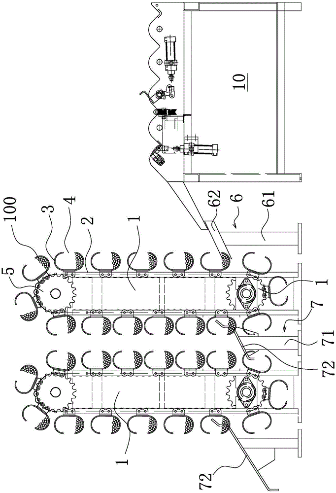
[0034] Such as figure 1 As shown, a storage rack for braided steel bars used in a pipe pile production line includes a storage rack body 1, and the storage rack body 1 is provided with a conveyor chain 2 that can rotate along the circumference of the storage rack body 1 and is transported The chain 2 is fixedly connected with a number of steel bar accommodation frames 3, and the steel bar accommodation frames 3 can support the weaving steel bars 100 so that the weaving cage steel bars 100 are placed in the steel bar accommodation frames 3. When one of the steel bars is accommodated When the number of caged steel bars of frame 3 reaches the set number, if it is necessary to compile a steel bar cage with 8 steel bars, then set the number of steel bar accommodation frame 3 to 8, and the conveyor chain 2 can drive the steel bar with the steel bar. Another steel bar storage frame 3 adjacent to the storage frame 3 arrives at the position of the steel bar storage frame 3, that is, af...

Embodiment 2

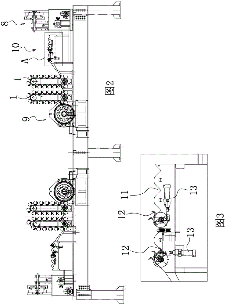
[0042] The structure and working principle of this embodiment are basically the same as that of Embodiment 1, the difference is that, as figure 2 As shown, the present embodiment provides a cage weaving steel bar conveying device, and the two sides of the storage rack body 1 are respectively provided with a steel bar pier 8 and a cage weaving machine 9 . Reinforcing bar pier machine 8 and weaving cage machine 9 are prior art, no longer repeat them here. What this embodiment provides is through automatic storage after the steel bar is processed by the pier head, and then automatically unloads the automatic conveying device to the cage machine 9. As mentioned above, the cage steel bar 100 is exported by the discharge guide plate 72, when it is discharged When the material guide plate 72 position corresponds to the position of the weaving cage machine 9, the cage weaving steel bar 100 can be directly put into the weaving cage machine 9 to implement the weaving cage work.

[004...


PUM


Abstract

The invention belongs to the technical field of architecture and relates to a weaving cage rebar storage rack used for a pipe pile production line and a weaving cage rebar conveying device. The weaving cage rebar storage rack comprises storage rack bodies which are provided with conveying chains and a plurality of rebar accommodating frames, wherein the conveying chains can rotate in the circumferential direction of the storage rack bodies, and the multiple rebar accommodating frames are fixedly connected to the conveying chains. The rebar accommodating frames can support weaving cage rebar, so that the weaving cage rebar is placed in the rebar accommodating frames. When the amount of the weaving cage rebar in one of the rebar accommodating frames reaches a set number, the conveying chains can drive another rebar accommodating frame adjacent to the rebar accommodating frame to reach the position of the rebar accommodating frame. According to the weaving cage rebar storage rack used for the pipe pile production line and the weaving cage rebar conveying device, automatic continuous storage of the weaving cage rebar can be achieved, automatic feeding and automatic discharging are achieved, and the automation degree is greatly improved.

Description

technical field [0001] The invention belongs to the technical field of construction, and relates to a storage rack for braided steel bars and a conveying device for braided steel bars used in a pipe pile production line. Background technique [0002] The production process of existing prefabricated piles or pipe piles is as follows: [0003] 1. Measuring and mixing of concrete raw materials. According to the designed mix ratio, sand, stone, cement, water, admixtures and admixtures are accurately measured, and a concrete forced mixer is used to make fresh concrete with a low slump of 3cm to 5cm. The design requires concrete The strength grade is not lower than C60 or C80. [0004] 2. Fabrication of centrifugal square pile end plate. The production of the end plate of the pipe pile is basically the same, but the shape of the end plate of the square pile is square, and the counterbores of the prestressed main reinforcement are evenly distributed along the four sides and corn...

Claims


Application Information

Patent Timeline
Patent Type & Authority Applications(China)
IPC IPC(8): B65G17/46B65G17/36B65G17/26
CPCB65G17/26B65G17/36B65G17/46B65G2201/0217
Inventor 周兆弟
Owner 浙江兆弟技术有限公司
Why Eureka
Try Eureka