Crank arm assembly and power transmission self-locking mechanism using crank arm assembly

An arm assembly and self-locking technology, which is applied in mechanical equipment, transmission devices, belts/chains/gears, etc., can solve problems such as complex structures and achieve simple structures

Active Publication Date: 2016-05-11
HENAN PINGGAO ELECTRIC +2
View PDF6 Cites 1 Cited by
  • Summary
  • Abstract
  • Description
  • Claims
  • Application Information

AI Technical Summary

Problems solved by technology

[0003] In order to solve the deficiencies in the prior art, the object of the present invention is to provide a self-contained power transmission mechanism that solves the problem in the prior art that requires an additional locking structure for locking after the guide post is stretched out or retracted into place. locking mechanism, and the object of the present invention is also to provide a kind of crank arm assembly used in the power transmission self-locking mechanism

Method used


Image

  • Crank arm assembly and power transmission self-locking mechanism using crank arm assembly
  • Crank arm assembly and power transmission self-locking mechanism using crank arm assembly
  • Crank arm assembly and power transmission self-locking mechanism using crank arm assembly

Examples


Embodiment Construction

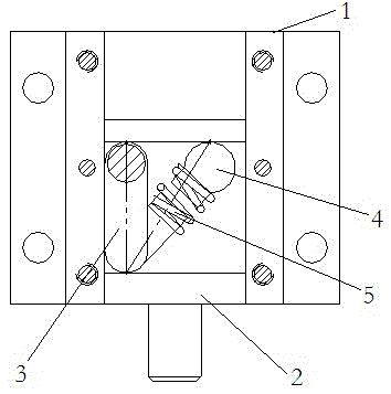
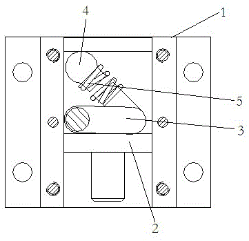
[0025] A power transmission self-locking mechanism of the present invention, such as figure 1 As shown, it includes a base 1, a guide post 2, a crank arm assembly 3 and a cover plate 19, and the base 1 is as Figure 7-9 As shown, the base 1 is provided with a chute 15 with left and right trough walls, and the guide post 2 guides and moves up and down and is assembled in the chute 15. The guide post 5 is as shown in FIG. Figure 5-6 As shown, it includes a guide rod part 2-1 for outputting linear motion downwards and a guide part 2-2 fixed on the upper end of the guide rod part 2-1 and cooperating with the guide movement of the chute 15. The guide part 2-2 is provided with There is a transmission groove 11 with upper and lower groove walls, and a crank arm assembly 3 is arranged in the transmission groove 11, and the crank arm assembly 3 is as Figure 3-4 As shown, it includes a power input shaft 7 whose axis for inputting torque to the crank arm assembly 3 extends in the fron...


PUM


Abstract

The invention relates to a crank arm assembly and a power transmission self-locking mechanism using the crank arm assembly. The power transmission self-locking mechanism comprises a guide post which can move up and down in a guiding mode. The guide post is provided with a transmission groove. The crank arm assembly is arranged inside the transmission groove and comprises a power input shaft, a connecting shaft, an installing shaft and a jacking head, wherein the connecting shaft is perpendicularly arranged on the power input shaft, and the jacking head is connected to the installing shaft through a spring and used for being in pushing fit with the upper groove wall of the transmission groove in the guide post in a sliding mode. When the crank arm assembly is located at an extending locking station, the upward force is applied to the upper groove wall of the transmission groove through the jacking head, the downward force is applied to the lower groove wall of the transmission groove through the tail end of the connecting shaft, and locking is conducted on the crank arm assembly in the extending position. When the crank arm assembly is located at a retracting locking station, the upward force is applied to the upper groove wall of the transmission groove through the jacking head, the downward force is applied to the lower groove wall of the transmission groove through the outer peripheral face of the connecting shaft, and locking is conducted on the crank arm assembly in the retracting position. According to the crank arm assembly and the power transmission self-locking mechanism using the crank arm assembly, an additional locking mechanism for locking a crank arm in the prior art is omitted, and the structure is simple.

Description

technical field [0001] The invention relates to a crank arm assembly and a power transmission self-locking mechanism using the crank arm assembly. Background technique [0002] In some mechanical equipment, a structure with a telescopic function of the guide column is often used. This structure generally needs to lock and position the guide post after the guide post is extended or retracted in place. For example, the motor drives the electric push rod, and the motor itself There is no locking structure for the electric push rod. At this time, an additional locking structure is often required, that is, more than two actions are required to complete the positioning process of extending and locking the guide column, resulting in the transmission structure. The structure is complex and the operation process is cumbersome. Contents of the invention [0003] In order to solve the deficiencies in the prior art, the object of the present invention is to provide a self-contained p...

Claims


Application Information

Patent Timeline
Patent Type & Authority Applications(China)
IPC IPC(8): F16H35/00
CPCF16H35/00
Inventor 张子明王婉怡
Owner HENAN PINGGAO ELECTRIC
Why Eureka
Try Eureka