Multi-zone vertical-alignment display panel and pixel structure thereof

A vertical alignment, display panel technology, applied in nonlinear optics, instruments, optics, etc., can solve problems such as affecting light transmittance, and achieve the effect of improving light transmittance

Inactive Publication Date: 2016-05-11
WUHAN CHINA STAR OPTOELECTRONICS TECH CO LTD
View PDF2 Cites 2 Cited by
  • Summary
  • Abstract
  • Description
  • Claims
  • Application Information

AI Technical Summary

Problems solved by technology

However, if figure 2 As shown, when the screen is displayed, due to the different tilting directions of liquid crystal molecules, dark lines 20 will appear at the junction of the main alignment region 12 and the sub-alignment region 14 and the junction of the sub-regions, so that there will be " Swastika-shaped dark line, which affects the light transmittance

Method used


Image

  • Multi-zone vertical-alignment display panel and pixel structure thereof
  • Multi-zone vertical-alignment display panel and pixel structure thereof
  • Multi-zone vertical-alignment display panel and pixel structure thereof

Examples


Embodiment Construction

[0023] The following descriptions of the various embodiments refer to the accompanying drawings to illustrate specific embodiments in which the present invention can be practiced. The directional terms mentioned in the present invention, such as "up", "down", "front", "back", "left", "right", "inside", "outside", "side", etc., are for reference only The orientation of the attached schema. Therefore, the directional terms used are used to illustrate and understand the present invention, but not to limit the present invention.

[0024] In the figures, structurally similar units are denoted by the same reference numerals.

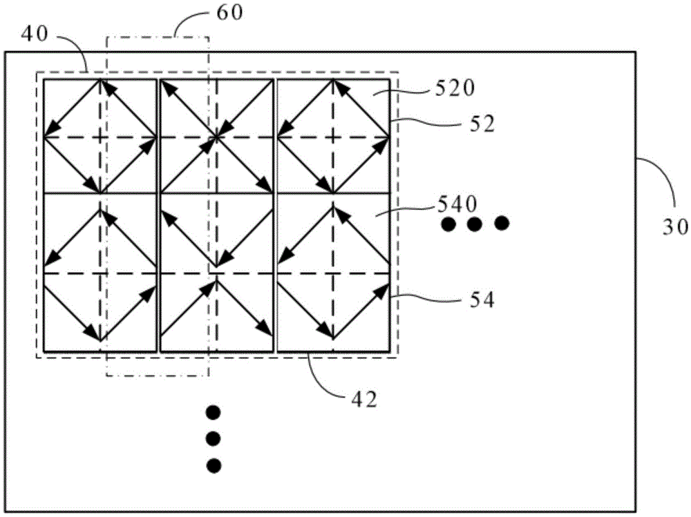
[0025] refer to image 3 , image 3 It is a schematic diagram of a multi-domain vertical alignment display panel according to a preferred embodiment of the present invention. The multi-region vertically aligned display panel 30 of the preferred embodiment of the present invention includes a plurality of pixel units 40 arranged in an array, and only one pix...


PUM


Abstract

The invention provides a multi-zone vertical-alignment display panel and a pixel structure thereof. The pixel structure comprises three sub-pixels arranged side by side, and each sub-pixel is formed by an upper alignment zone and a lower alignment zone. Each upper alignment zone comprises four sub-zones, each lower alignment zone comprises four sub-zones, the alignment directions of the up and down adjacent sub-zones and the left and right sub-zones of the corresponding four sub-zones are perpendicular, and the alignment directions of any two adjacent sub-zones located on the left and right adjacent sub-pixels respectively are identical. Dark lines between the left and right adjacent sub-pixels can be reduced, and the light transmittance is improved.

Description

【Technical field】 [0001] The invention relates to a display panel and a pixel structure thereof, in particular to a display panel with multi-region vertical alignment induced by ultraviolet rays and a pixel structure thereof. 【Background technique】 [0002] Thin film transistor liquid crystal (TFT-LCD) displays have been developed rapidly and widely used in recent years. Specifically, TFT-LCD can be regarded as a layer of liquid crystal sandwiched between two glass substrates, the upper glass substrate is a color filter, and the lower glass substrate is provided with a thin film transistor. When the current passes through the thin film transistor, a change in the electric field is generated, and the change in the electric field causes the liquid crystal molecules to deflect, thereby changing the polarity of the light and realizing the expected display screen. Before the voltage is applied, the liquid crystal molecules need to have an initial alignment direction. Therefore, ...

Claims


Application Information

Patent Timeline
Patent Type & Authority Applications(China)
IPC IPC(8): G02F1/1337
CPCG02F1/1337G02F1/133753G02F1/133757G02F1/133788
Inventor 张鑫赵勇刘秉德
Owner WUHAN CHINA STAR OPTOELECTRONICS TECH CO LTD
Why Eureka
Try Eureka