Motor, rotor and installation method of rotor

An installation method and rotor technology, which are applied in electromechanical devices, manufacturing motor generators, manufacturing stator/rotor bodies, etc., can solve problems such as misalignment of inner and outer rotor cores, deterioration of rotor dynamic balance, and reduced reliability, so as to ensure operation Reliability, ensuring dynamic balance performance, and avoiding misalignment

Active Publication Date: 2016-05-11
GREE ELECTRIC APPLIANCES INC
View PDF5 Cites 4 Cited by
  • Summary
  • Abstract
  • Description
  • Claims
  • Application Information

AI Technical Summary

Problems solved by technology

[0003] At present, the vibration damping structure cannot guarantee the accurate alignment of the inner rotor core and the outer rotor core during injection molding. During the injection process, the inner and outer rotor cores are prone to misalignment, resulting in poor dynamic balance of the rotor and poor reliability. reduce

Method used


Image

  • Motor, rotor and installation method of rotor
  • Motor, rotor and installation method of rotor
  • Motor, rotor and installation method of rotor

Examples


Embodiment Construction

[0034] The core of the invention is to provide a rotor to avoid misalignment and ensure the reliability of the rotor operation. The invention also provides a motor with the above-mentioned rotor and a method for installing the rotor.

[0035] In order to enable those skilled in the art to better understand the solution of the present invention, the present invention will be further described in detail below in conjunction with the accompanying drawings and specific embodiments.

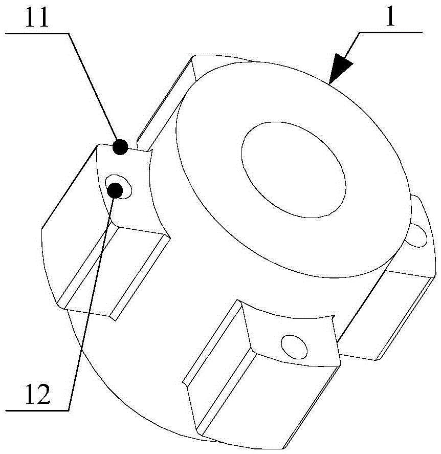
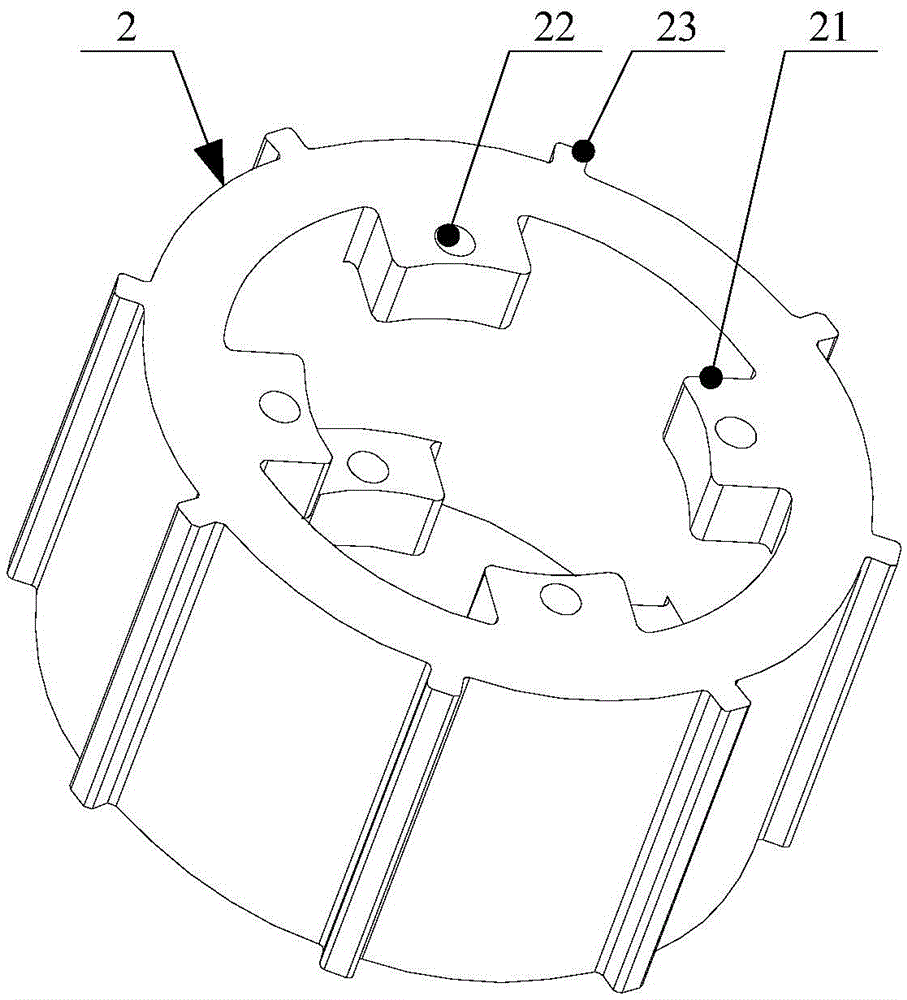
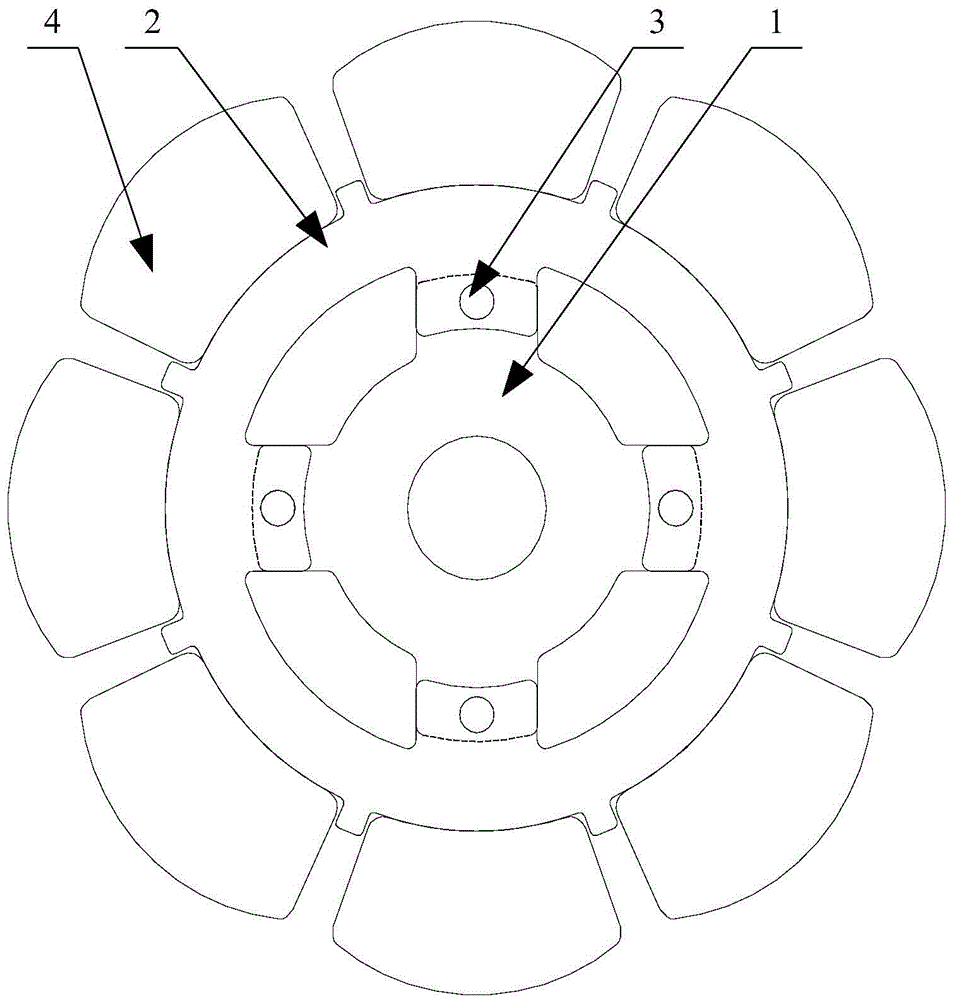
[0036] Please refer to figure 1 , figure 2 and image 3 , figure 1 Schematic diagram of the structure of the inner rotor core provided by the present invention; figure 2 Schematic diagram of the structure of the outer rotor core provided by the present invention; image 3 It is a schematic structural diagram of the rotor provided by the present invention before glue injection.

[0037] In this specific embodiment, the rotor includes an inner rotor core 1 and an outer rotor core 2, the outer wa...


PUM


Abstract

The invention discloses a motor, a rotor and an installation method of the rotor. The rotor comprises an inner rotor iron core (1) and an outer rotor iron core (2), wherein a plurality of inner rotor bosses (11) distributed uniformly are arranged on the outer wall of the inner rotor iron core (1), first positioning holes (12) are formed in the inner rotor bosses (11), outer rotor bosses (21) are arranged on the inner wall of the outer rotor iron core (2) and are in one-to-one correspondence to the inner rotor bosses (11), the outer rotor bosses (21) and the inner rotor bosses (11) are staggered in an axial direction, and second positioning holes (22) are formed in the outer rotor bosses (21) and arranged corresponding to the first positioning holes. With the rotor provided by the invention, the inner rotor bosses and the outer rotor bosses are prevented from being mismatched, the rotor dynamic balance performance is ensured, and the running reliability of the rotor is ensured.

Description

technical field [0001] The invention relates to the technical field of motor equipment, in particular to a motor, a rotor and a method for installing the rotor. Background technique [0002] In order to weaken the torque ripple of the motor and improve the sound quality of the load, the damping rotor uses rubber and other elastic buffer materials to inject the inner rotor core and the outer rotor core into one body, and reduces the impact of load torque ripple on the load through the buffer material. impact, thereby improving load sound quality. [0003] At present, the vibration damping structure cannot guarantee the accurate alignment of the inner rotor core and the outer rotor core during injection molding. During the injection process, the inner and outer rotor cores are prone to misalignment, resulting in poor dynamic balance of the rotor and poor reliability. reduce. [0004] Therefore, how to avoid misalignment and ensure the operational reliability of the rotor is ...

Claims


Application Information

Patent Timeline
Patent Type & Authority Applications(China)
IPC IPC(8): H02K1/27H02K15/03
CPCH02K1/27H02K15/03
Inventor 高晓峰王周叶许学刚任丽君
Owner GREE ELECTRIC APPLIANCES INC
Why Eureka
Try Eureka