Fold-back ventilating device of collective escaping chamber

A ventilation device and escape cabin technology, which can be used in water rescue, transportation and packaging, ships, etc. It can solve the problems of poor machining accuracy and sealing effect, poor operating reliability of escape cabins, and limited height of ventilation holes, etc., to ensure dynamic balance , to avoid adverse effects, the effect of large output load

Active Publication Date: 2014-07-16
中国船舶重工集团公司第七〇二研究所
View PDF8 Cites 2 Cited by
  • Summary
  • Abstract
  • Description
  • Claims
  • Application Information

AI Technical Summary

Problems solved by technology

[0004] At present, domestic research on deep-sea escape equipment mostly focuses on the research and development of the overall structural form of the escape cabin, but there is very little research on the ventilation device, such as the "sea non-reversible escape cabin" disclosed in Chinese patent ZL 200420013990.4. The air exchange device above the sea level is equipped with a threaded inner casing and an outer casing on the top of the cabin. By manually rotating the inner casing, the inner casing can be raised or lowered relative to the outer casing on the top of the cabin. Therefore, the air exchange hole on the inner casing is exposed to the water surface, thereby realizing air exchange. However, this air exchange device has the following defects: First, the manual rotation directly drives the air exchange hole to rise, and the output load is small, so the air exchange hole rises. The height is very limited; second, the inner casing and the outer casing rotate relatively, so a dynamic sealing structure is required for sealing, and the dynamic sealing structure has the problems of high machining accuracy and poor sealing effect. Under the underwater working environment, the use of The escape cabin with dynamic sealing structure has poor working reliability and is inconvenient to overhaul

Method used


Image

  • Fold-back ventilating device of collective escaping chamber
  • Fold-back ventilating device of collective escaping chamber
  • Fold-back ventilating device of collective escaping chamber

Examples


Embodiment Construction

[0028] The specific implementation manner of the present invention will be described below in conjunction with the accompanying drawings.

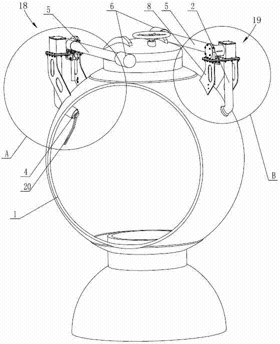
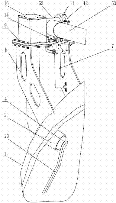
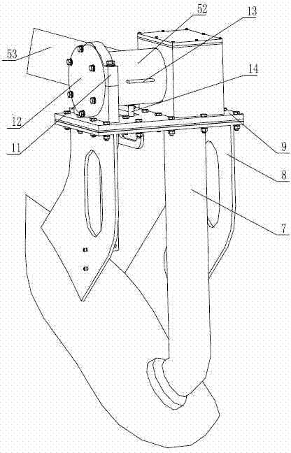
[0029] See figure 1 , the present invention includes an air intake system 18 and an exhaust system 19 connected to the escape cabin body 1, see figure 2 , image 3 , Figure 4 , the air intake system 18 includes a connecting pipe 2, one end of the connecting pipe 2 extends into the escape cabin body 1, and the other end communicates with the conversion cavity 3 outside the escape cabin body 1, the conversion cavity 3 is a closed space, and extends into the escape cabin body The end of the connecting pipe 2 in 1 is equipped with a screw plug 4, and the screw plug 4 can be installed or removed by rotating the handle 20. For the specific connection structure between the connecting pipe 2 and the screw plug 4, see Figure 5 , the connecting pipe 2 is threadedly connected with the screw plug 4, the connecting pipe 2 is provided with a plug ...


PUM


Abstract

The invention discloses a fold-back ventilating device of a collective escaping chamber. The fold-back ventilating device comprises an air inlet system and an air outlet system which are connected with an escaping chamber body and have a same structure, wherein the air inlet system comprises a connecting pipe; one end of the connecting pipe stretches into the chamber, and the other end of the connecting pipe is communicated with a closed conversion cavity outside the chamber; a screw plug is arranged at the end of the connecting pipe in the chamber; the conversion cavity is communicated with a horizontal ventilating duct; the ventilating duct and the conversion cavity are connected in a sealed and rotatable mode, and a radial ventilating hole is formed in the other end of the ventilating duct; a waterproof cover sleeves the end of the ventilating duct and covers the radial ventilating hole; a piston rod of a vertical cylinder is hinged with the ventilating duct; a cylinder body is hinged with a lower mounting seat; the lower mounting seat is fixedly arranged on the escaping chamber body; the conversion cavity is fixedly arranged on the lower mounting seat; when the escaping chamber floats to the water surface and needs ventilation, the screw plug in the air inlet system and the air outlet system is removed, and the connecting pipe in the chamber of the air outlet system and an air outlet pipe of an air blower in the chamber are connected with each other. Ventilation inside and outside the chamber can be realized under the condition that a chamber cover is not opened, and the operation is stable and reliable.

Description

technical field [0001] The invention relates to deep-sea escape equipment, in particular to a collective escape cabin of a deep-sea space station, and in particular to a ventilation device for realizing air circulation inside and outside the cabin after the collective escape cabin floats to the water surface. Background technique [0002] As an independent and self-contained escape device, the collective escape cabin can effectively improve the self-rescue ability of the wrecked crew and ensure the safety of the personnel during the escape process, which is superior to any previous escape equipment. [0003] Due to the small displacement and low freeboard of the escape cabin, after the escape cabin was released and floated to the water surface, the escape cabin was in a state of waiting for rescue on the water surface. In order to prevent waves from entering the cabin, the upper hatch cover could not be opened for natural ventilation. , in order to prolong the waiting time a...

Claims


Application Information

Patent Timeline
Patent Type & Authority Applications(China)
IPC IPC(8): B63C9/06
Inventor 张震王永军吴世海
Owner 中国船舶重工集团公司第七〇二研究所
Why Eureka
Try Eureka