
Angular contact ball bearing

A technology of angular contact ball bearings and oil injection holes, which is applied to bearing components, shafts and bearings, mechanical equipment, etc., can solve problems such as bearing heating, oil mist pollution, and working environment hazards, and achieve the effect of reducing speed and avoiding waste

Active Publication Date: 2016-12-14
LUOYANG BEARING RES INST CO LTD
View PDF12 Cites 2 Cited by
  • Summary
  • Abstract
  • Description
  • Claims
  • Application Information

AI Technical Summary

Problems solved by technology

In the above lubricating structure, the lubricating oil is sprayed directly into the bearing through the oil nozzle at high pressure. This lubricating method has many shortcomings: (1) The high-pressure liquid flow collides with the airflow formed by the high-speed rotation of the bearing, resulting in a large Loud howling sound, which is the most important and worst part of the noise of high-speed bearings, is also very harmful to human hearing; (2) The high-pressure and high-speed liquid flow formed by the high-pressure lubricating oil through the nozzle directly Spraying onto the high-speed rotating steel balls and cages will vibrate the steel balls and cages, affecting the machining accuracy of the machine tool; (3) The high-pressure liquid flow collides with the airflow formed by the high-speed rotation of the bearing or the high-speed rotating steel balls, causing Strong oil mist pollution is very harmful to the working environment; (4) Lubrication of high-speed bearings does not require a large amount of lubricating oil. If the amount of lubricating oil is too large, it will not only cause a lot of waste, but also may cause the lubricating oil to whirl and dissipate heat Not good, cause the bearing to heat up

Method used


Image

  • Angular contact ball bearing
  • Angular contact ball bearing
  • Angular contact ball bearing

Examples


Embodiment Construction

[0026] The embodiments of the present invention will be further described below with reference to the accompanying drawings.

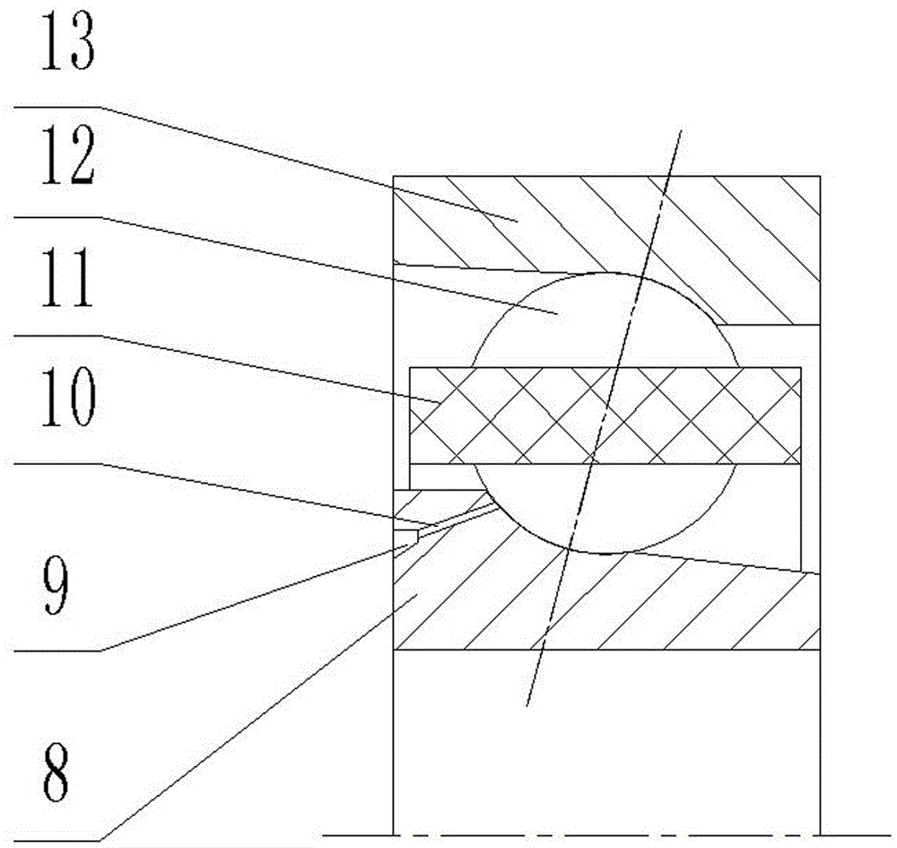
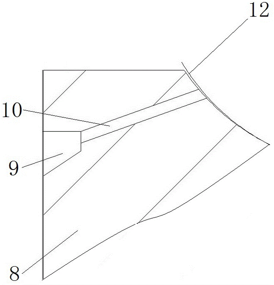
[0027] The specific embodiment 1 of the angular contact ball bearing of the present invention, such as Figure 2 to Figure 5 As shown, 8 is the inner ring, 9 is the annular groove, 10 is the oil injection hole, 11 is the cage, 12 is the ceramic ball, 13 is the outer ring, and 14 is the fuel injection nozzle.

[0028] This embodiment adopts a high-speed bearing that is conducive to heat dissipation. Both the inner ring 8 and the outer ring 13 of the bearing are provided with concave surfaces, the concave surfaces correspond to the rolling elements, and the concave surfaces include a working area and a non-working area that are used to cooperate with the rolling elements to support and guide the rolling elements. , The rolling body adopts ceramic ball 12 with excellent high-speed performance. The end surface of the inner ring 8 is distributed with annul...


PUM


Abstract

The invention provides an angular contact ball bearing in order to reduce noise generated when the angular contact ball bearing operates. The angular contact ball bearing comprises an inner ring, an outer ring and oil injection holes formed in the inner ring or the outer ring; inlets of the oil injection holes are located in the end surface of the inner ring or the outer ring; outlets of the oil injection holes are located in the concave surface, corresponding to a rolling body, of the inner ring or the outer ring; and the outlets of the oil injection holes fall behind the inlets in the rotation direction of the inner ring or the outer ring where the oil injection holes are formed. The outlets of the oil injection holes fall behind the inlets in the rotation direction of the inner ring or the outer ring, lubricating oil in the oil injection holes can be thrown towards a rolling ball of the bearing by a backward throwing force generated when the inner ring or the outer ring rotates, so that the lubricating oil automatically enters the rolling ball of the bearing to realize lubrication; and compared with the existing high-speed jet oil injection way, the angular contact ball bearing has the advantages that the speed of the lubricating oil is reduced, and no relatively high noise can be generated after airflow collision caused when the bearing rotates.

Description

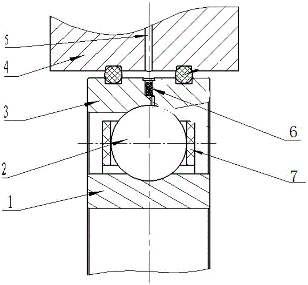
technical field [0001] The invention relates to an angular contact ball bearing. Background technique [0002] The development of high-speed and precision CNC machine tools requires bearings to have higher speed characteristics and lower noise. For angular contact ball bearings with traditional structures, the bearings need to be lubricated during high-speed operation, which can reduce the friction between the rolling elements and the inner and outer rings. At the same time, the flow of the lubricating medium can take away the heat generated by the rotation of the rolling elements. The oil injection hole is often opened on the inner ring or outer ring of the bearing. like figure 1 The existing oil injection structure is shown, in which 1 is the inner ring, 2 is the rolling body, 3 is the outer ring, 7 is the cage, and an oil injection hole 6 is opened in the circumferential direction of the outer ring 3, and the inlet of the oil injection hole 6 is located in the outer rin...

Claims


Application Information

Patent Timeline
IPC IPC(8): F16C33/66
Inventor 王东峰商琪尹延经杨浩亮焦春照
Owner LUOYANG BEARING RES INST CO LTD
Learn More