

Motorcycle
A technology for motorized two-wheeled vehicles and rear wheels, applied to motor vehicles, electric scooters, bicycles, etc., can solve the problems of complex structure, increased plate thickness, etc., and achieve the effects of suppressing vibration, simple shape, and improving rigidity
- Summary
- Abstract
- Description
- Claims
- Application Information
AI Technical Summary
Problems solved by technology
Method used
Image

Examples
Embodiment 1
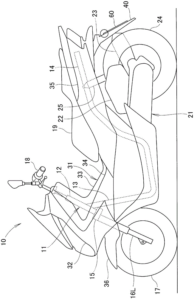
[0054] Such as figure 1 As shown, the motorcycle 10 includes a frame 11 , a power unit 21 that is swingably suspended from the rear of the frame 11 , and a body cover 31 that covers the frame 11 .
[0055] The frame 11 is composed of: a steering stem 12 ; a main frame 13 extending rearward and downward from the steering stem 12 ; and a seat rail 14 extending rearward and upward from the rear end of the main frame 13 .
[0056] The front fork 16L (hereinafter, L is an additional symbol indicating left, and R is an additional symbol indicating right.) is supported on the lower part of the steering stem 12 via the lower link plate 15, and the front fork 16L is rotatably supported by a front fork 16L. round 17. In addition, a handle 18 for steering the front wheels 17 is provided on an upper portion of the steering standpipe 12 , and a seat 19 on which a passenger sits is provided on an upper portion of the seat rail 14 .
[0057]The power unit 21 includes an air cleaner 22 for ...
Embodiment 2
[0078] Next, the motorcycle of Example 2 will be described, but the same components as those of the motorcycle of Example 1 will be described by assigning the same reference numerals.
[0079] Such as Figure 13 As shown, the plate member 60b is a license plate 60b on which information identifying the vehicle is described. The license plate 60b has a rectangular flat portion 61b marked with a character string, an edge portion 62b reinforcing the periphery of the flat portion 61b, and through holes 66b formed in the left and right upper portions of the flat portion 61b. The license plate 60b has a longitudinal length L2 and a lateral length W2.
[0080] Such as Figure 14 As shown, the fastening member 68b passes through the through hole 66b through the nut 74b from the back surface 64b of the license plate 60b, and is fixed by a pin covered by a cap 69b provided on the front side of the license plate 60b.
[0081] Such as Figure 15 As shown, inserts are used during inject...
Embodiment 3
[0085] Next, the motorcycle of Example 3 will be described, but the same components as those of the motorcycle of Example 1 will be described by assigning the same reference numerals.
[0086] Such as Figure 19 , Figure 20 As shown, the plate member 60c is a license plate 60c on which information identifying the vehicle is described. The license plate 60c has a rectangular flat portion 61c marked with a character string, an edge portion 62c that reinforces the periphery of the flat portion 61c, and through holes 66c formed in the left and right upper portions of the flat portion 61c. The license plate 60c has a longitudinal length L3 and a lateral length W3.
[0087] Such as Figure 21 As shown, inserts are used during injection molding, so that the second mounting part of the rear fender 40 ( Figure 9 , Reference numeral 53) penetrates through, thereby forming the mounting hole 55c on the rear fender 40. Only the mounting holes 55c are opened on the rear surface 43 of...
PUM
 Abstract
Description
Claims
Application Information