Cable lug device having current bar, and connection terminal

A terminal and terminal technology, which is applied to the parts of the connection device, the coupling device, the conductive connection, etc., can solve the problems of difficult contact and heating of the contact terminal, and achieve the effects of low cost, safe operation, and improved operation safety.

Inactive Publication Date: 2016-05-11
PHOENIX CONTACT GMBH & CO KG
View PDF5 Cites 1 Cited by
  • Summary
  • Abstract
  • Description
  • Claims
  • Application Information

AI Technical Summary

Problems solved by technology

Terminals may experience contact difficulties at certain terminal transitions, resulting in localized heating of the contact terminals

Method used


Image

  • Cable lug device having current bar, and connection terminal
  • Cable lug device having current bar, and connection terminal
  • Cable lug device having current bar, and connection terminal

Examples


Embodiment Construction

[0064] The structure and function of the cable lug device equipped with the current bar 310 and the terminal 100 will be described below with reference to the accompanying drawings, and the current bar 310 is provided for the terminal 100 through the cable lug device 300 . The connection terminal 100 is designed here as a lead terminal and is used, for example, to connect cables to electrical appliances.

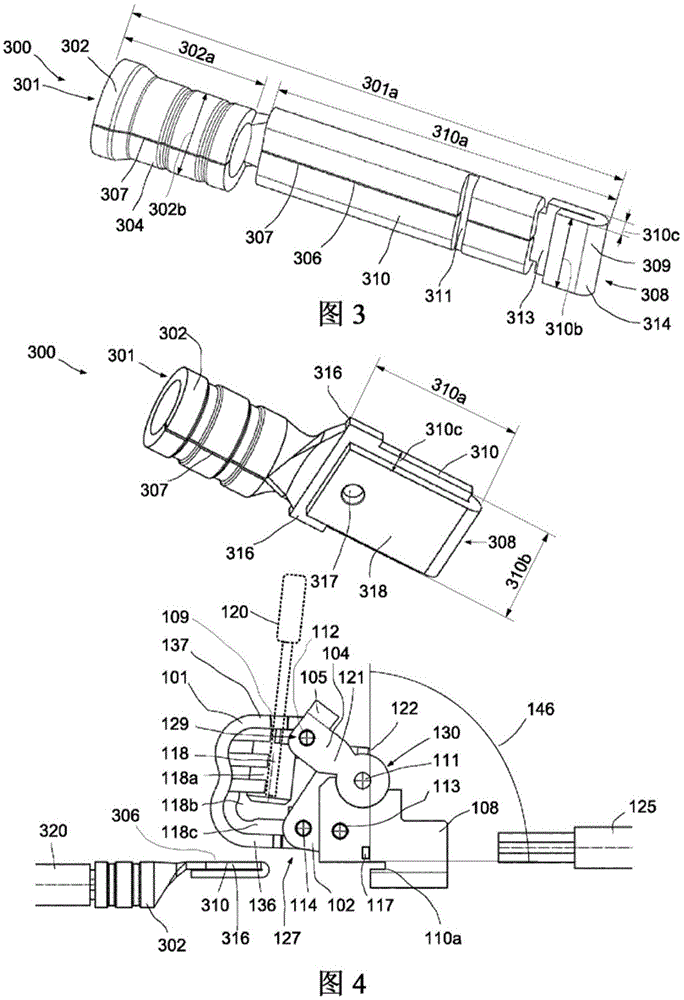
[0065] During assembly, the cable lug device 300 is first inserted into the terminal 100 with the current bar provided thereon, and then the wire 126 to be connected clamped between the clamping device of the terminal 100 and the current bar 310 is inserted into the terminal 100. terminals. Wherein, the current bar 310 of the cable lug device 300 is supported on the bracket 108 .

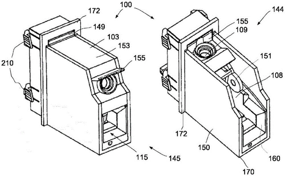
[0066] in, figure 1 Two perspective views of the connection terminal 100 are shown side by side, namely on the left in the clamped state or in the contact position 145 and on the right in the op...


PUM


Abstract

A cable lug device (300) and connection terminal (100) having a cable lug device (300), the connection terminal having a conductor receptacle (115), a clamping device (101) and a current bar receptacle (110a). On the connection terminal is provided a cable lug device (100) having a cable lug body (301) and, provided thereon, a cable receptacle (302) for fastening a connection cable (303). The cable lug body (301) has a current bar (310) that is inserted in a current bar receptacle (110a) of the connection terminal (100) and serves there as a current bar (110) for contacting a conductor (126).

Description

technical field [0001] The invention relates to a cable lug arrangement with a current bar and to a terminal with such a cable lug arrangement for connecting at least one conductor. The current bar of the cable lug device and the electrical connection terminal are particularly suitable for connecting conductors with a large cross-section. Wherein, the electrical connection terminal can be used for and is suitable for wires with a small cross-section, but is especially suitable for wires with a cross-section up to 25 mm. 2 even 50mm 2 of wires. Background technique [0002] Various terminal blocks are known in the prior art which are suitable for connecting conductors with large cross-sections. Such terminal blocks are especially used in high current areas where pulsed currents up to 80,000 amperes may occur. [0003] In addition to the price of the terminal block, safety is also an important factor when designing and manufacturing suitable terminal blocks. Terminals may...

Claims


Application Information

Patent Timeline
Patent Type & Authority Applications(China)
IPC IPC(8): H01R4/48H01R13/04
CPCH01R13/04H01R4/48185H01R4/183H01R4/28H01R4/4809H01R13/629
Inventor 拉尔夫·贝克曼安德列亚斯·文特
Owner PHOENIX CONTACT GMBH & CO KG
Why Eureka
Try Eureka