Winding demoulding machine of winding glass steel tube demoulding machine

A glass steel pipe and stripping machine technology, which is applied in the field of winding and stripping machine for winding glass steel pipe stripping machine, can solve the problems of hidden dangers of operator safety, hidden danger of product quality and high demoulding cost, and achieves the improvement of demoulding efficiency and speed, Wide application range and good demoulding quality

Active Publication Date: 2016-05-18
SUZHOU KUAIJIE AUTOMATION EQUIP CO LTD
View PDF8 Cites 9 Cited by
  • Summary
  • Abstract
  • Description
  • Claims
  • Application Information

AI Technical Summary

Problems solved by technology

When demolding, turn the handle rod to make the screw rod rise upwards, and drive the top block to exert a jacking force on the composite material product. As the top block rises, the part of the composite material product that is detached from the mold will gradually expand, and then try to apply an appropriate force. Auxiliary prying force can smoothly separate the composite material product from the forming mold. Although there are many demolding methods and equipment, there are not many that are really efficient, automated, and cost-saving, which cannot meet the requirements for mass production of large pipes.
This makes each demoulding cost high and time-consuming, and the brutal demoulding operation will cause damage to the product or the mandrel, and will also bring safety hazards to the operator and quality hazards to the product.

Method used


Image

  • Winding demoulding machine of winding glass steel tube demoulding machine
  • Winding demoulding machine of winding glass steel tube demoulding machine
  • Winding demoulding machine of winding glass steel tube demoulding machine

Examples


Embodiment Construction

[0029] The following will clearly and completely describe the technical solutions in the embodiments of the present invention with reference to the accompanying drawings in the embodiments of the present invention. Obviously, the described embodiments are only some, not all, embodiments of the present invention. Based on the embodiments of the present invention, all other embodiments obtained by persons of ordinary skill in the art without creative efforts fall within the protection scope of the present invention.

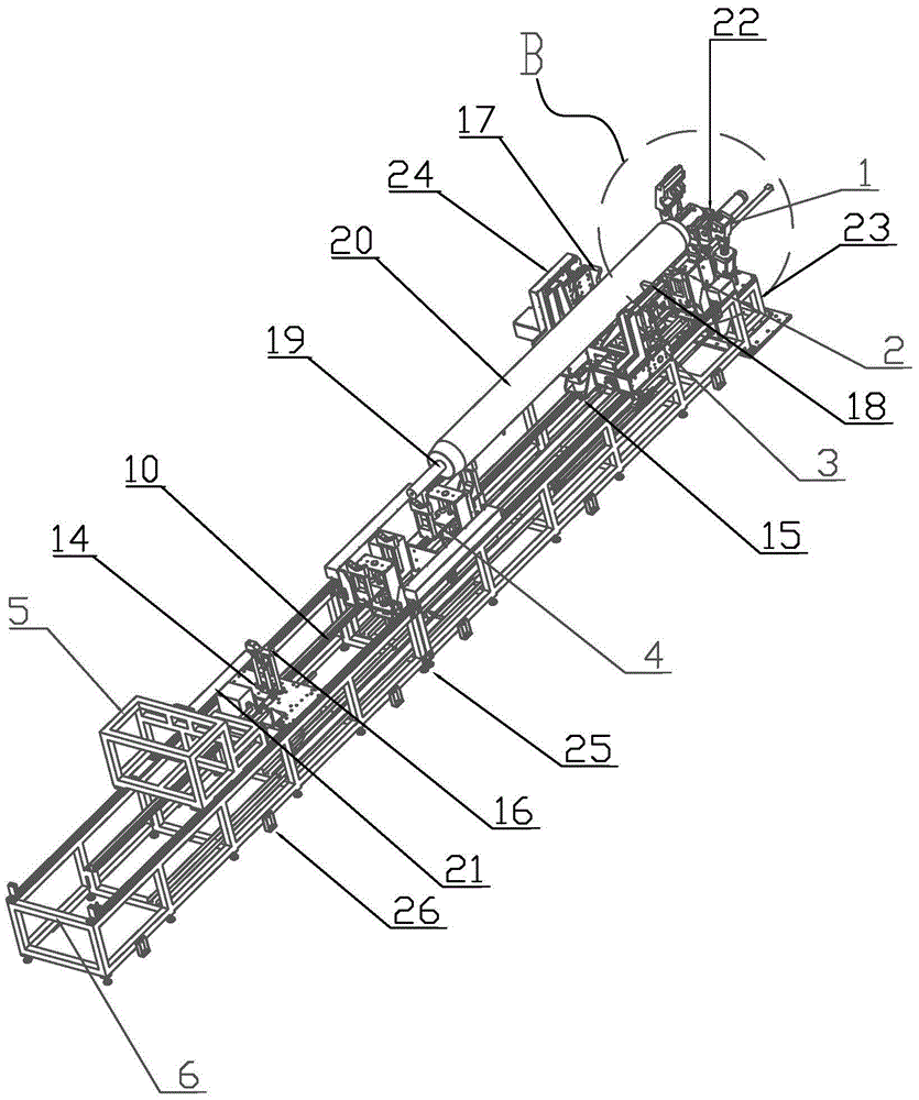
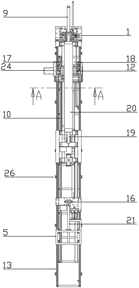
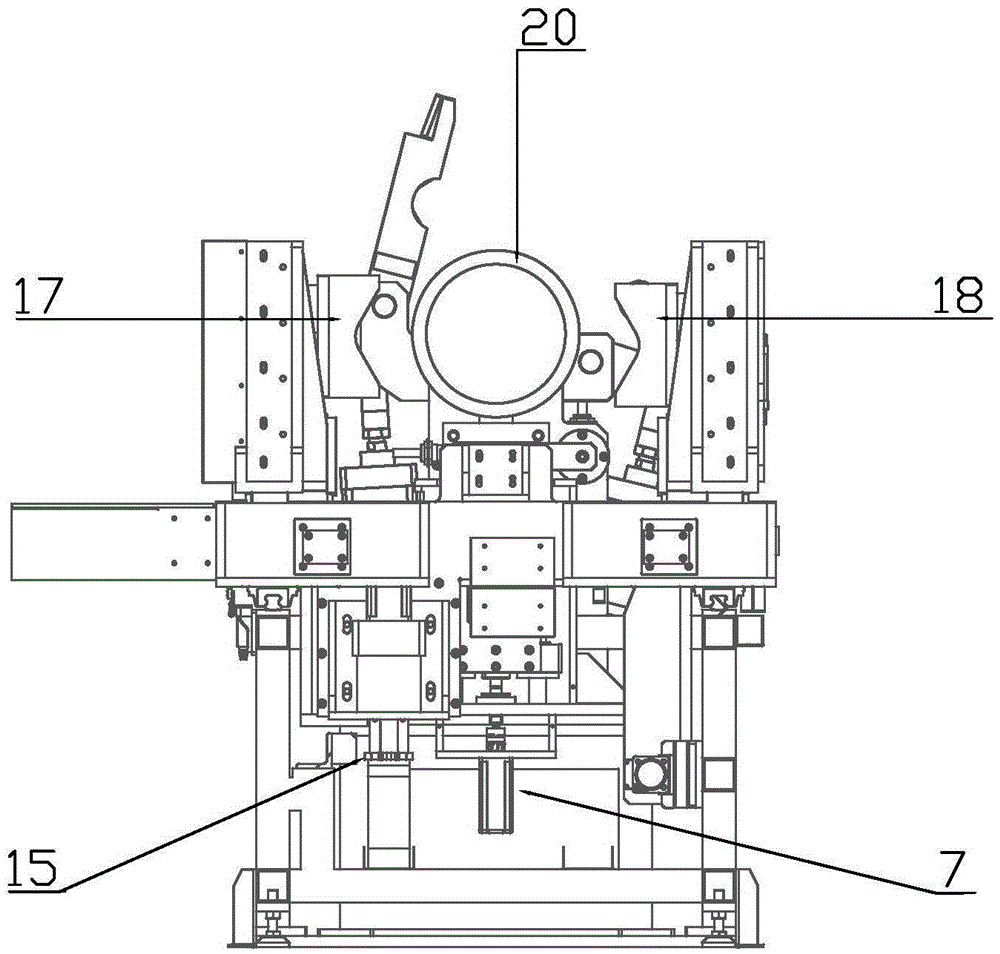
[0030] according to figure 1 , figure 2 , image 3 and Figure 4 , the invention provides a winding demoulding machine for glass steel pipes, comprising a mandrel clamping mechanism 1, a front support frame 2, a clamping demoulding mechanism 3, a moving support 4, a mandrel tail frame 5, a demoulding Machine frame 6, servo motor 7, cylinder 8, hydraulic cylinder 9, rack 10, cylinder spring 11, screw rod 12, linear slide rail 13, linear bearing 14, gear 15, tail...


PUM

PropertyMeasurementUnit
lengthaaaaaaaaaa

Abstract

The invention discloses a winding demoulding machine of a winding glass steel tube demoulding machine. The winding demoulding machine comprises core mould clamping mechanisms, a front supporting rack, a clamping demoulding mechanism, a movable support, a core mould tail rack, a demoulding machine framework, a rack, a lead screw, a linear sliding rail, a tail supporting rack and a controller. A clamping frame, a clamping base and the front supporting rack are arranged at the front end of the demoulding machine framework, and the core mould clamping mechanisms are arranged on the two sides of the clamping base. The linear sliding rail is disposed on the side edge of the demoulding machine framework, and the rack is arranged on the inner side face of the demoulding machine framework. The clamping demoulding mechanism, the movable support, the tail supporting rack and the core mould tail rack are sequentially arranged on the linear sliding rail. A gear, a servo motor and a displacement sensor are disposed below the clamping demoulding mechanism, the movable support, the tail supporting rack and the core mould tail rack respectively. The controller is arranged on the clamping demoulding mechanism, and a control program is set in the controller. Automatic demoulding is achieved, demoulding efficiency is high, demoulding speed is high, and the winding demoulding machine is suitable for large-scale demoulding, good in demoulding quality and wide in application range.

Description

technical field [0001] The invention relates to the field of glass steel pipe technical equipment of a winding glass steel pipe demoulding machine, in particular to a winding glass steel pipe demoulding machine winding demoulding machine. Background technique [0002] With the wide application of glass steel pipes, its production and manufacturing technology is also constantly improving. There are many demoulding methods for glass steel pipes. The commonly used demoulding methods are: manual demoulding, mechanical demoulding, air pressure Law. The mechanical demoulding usually uses the traction force of mechanical equipment such as screw device, hoist or crane to pull the mold to complete the demoulding process. If the composite material pipe is wound by the mandrel, one end of the mandrel can be connected with the tailstock of the special equipment for demoulding, and the composite pipe product is positioned, and the mandrel is pulled out at a uniform speed by the traction...

Claims


Application Information

Patent Timeline
Patent Type & Authority Applications(China)
IPC IPC(8): B29C33/44
CPCB29C33/44
Inventor 邵春刚
Owner SUZHOU KUAIJIE AUTOMATION EQUIP CO LTD
Why Eureka
Try Eureka