
Electronic expansion valve

An electronic expansion valve, valve cavity technology, applied in valve details, safety valve, balance valve and other directions, can solve problems such as electronic expansion valve failure, and achieve the effect of eliminating failure

Inactive Publication Date: 2016-05-18
ZHEJIANG SANHUA INTELLIGENT CONTROLS CO LTD
View PDF14 Cites 13 Cited by
  • Summary
  • Abstract
  • Description
  • Claims
  • Application Information

AI Technical Summary

Problems solved by technology

[0008] The main purpose of the present invention is to provide an electronic expansion valve to solve the problem in the prior art that the electronic expansion valve fails due to impurities entering the auxiliary valve cavity

Method used


Image

  • Electronic expansion valve
  • Electronic expansion valve
  • Electronic expansion valve

Examples


Embodiment Construction

[0033] It should be noted that, in the case of no conflict, the embodiments in the present application and the features in the embodiments can be combined with each other. The present invention will be described in detail below with reference to the accompanying drawings and examples.

[0034] It should be noted that the terminology used here is only for describing specific embodiments, and is not intended to limit exemplary embodiments according to the present invention. As used herein, unless the context clearly indicates otherwise, the singular form is also intended to include the plural form. In addition, it should also be understood that when the terms "comprising" and / or "comprising" are used in this specification, it indicates There are features, steps, operations, means, components and / or combinations thereof.

[0035] For the convenience of description, spatially relative terms may be used here, such as "on ...", "over ...", "on the surface of ...", "above", etc., to...


PUM


Abstract

The invention provides an electronic expansion valve. The electronic expansion valve comprises a shell, a valve seat, a valve needle and a rotor assembly. The valve seat, the valve needle and the rotor assembly are located in the shell. The rotor assembly drives the valve needle to be matched with the valve seat. The inner space of the shell comprises a main valve cavity and an auxiliary valve cavity. The valve seat is located in the main valve cavity. The rotor assembly is located in the auxiliary valve cavity. The electronic expansion valve further comprises a filtration device. The filtration device is located between the main valve cavity and the auxiliary valve cavity to filter fluid entering the auxiliary valve cavity from the main valve cavity. Due to the fact that the electronic expansion valve comprises the filtration device which is located between the main valve cavity and the auxiliary valve cavity to filter the fluid entering the auxiliary valve cavity from the main valve cavity, impurities in a system where the electronic expansion valve is located cannot enter the auxiliary valve cavity; therefore, the problem that the electronic expansion valve loses efficacy due to the fact that the impurities enter the auxiliary valve cavity can be solved on the basis of ensuring that the main valve cavity and the auxiliary valve cavity communicate with each other.

Description

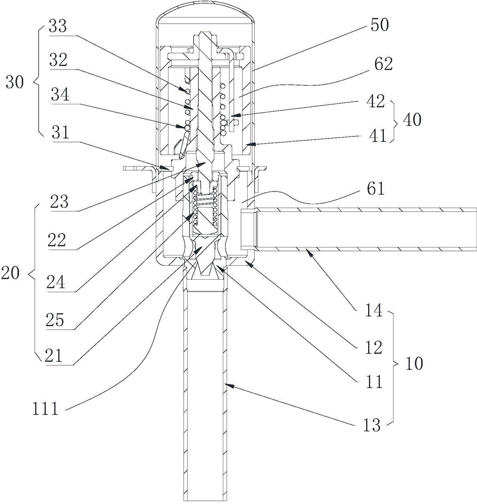
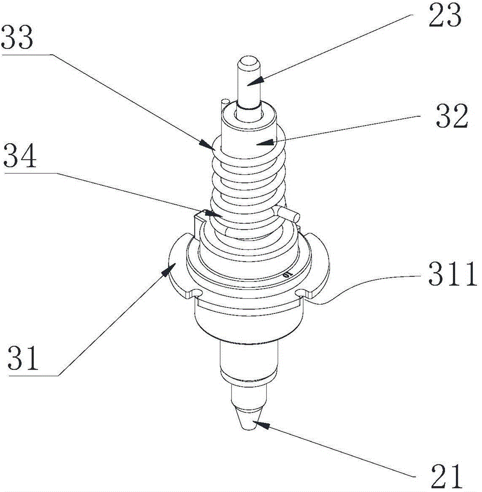
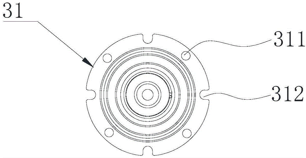
technical field [0001] The invention relates to the field of valve equipment, in particular to an electronic expansion valve. Background technique [0002] Electronic expansion valve is a component commonly used to regulate fluid flow in refrigeration or heating devices such as air conditioners, refrigerators, and heat pump water heaters. Figure 1 to Figure 3 The structure of a commonly used electronic expansion valve in the prior art is shown. [0003] Such as Figure 1 to Figure 3 As shown, the electronic expansion valve includes a valve seat assembly 10 , a valve needle screw assembly 20 , a nut assembly 30 , a rotor assembly 40 and an upper shell 50 . [0004] The valve seat assembly 10 includes a valve core seat 11 , a valve seat shell 12 , a first connecting pipe 13 and a second connecting pipe 14 . A valve seat 111 is arranged on the valve core seat 11 . The valve needle screw assembly 20 includes a valve needle 21 , a valve needle sleeve 22 , a screw rod 23 , a re...

Claims


Application Information

Patent Timeline
Patent Type & Authority Applications(China)
IPC IPC(8): F16K17/20F16K31/02B01D35/04
Inventor 张亚波
Owner ZHEJIANG SANHUA INTELLIGENT CONTROLS CO LTD
Learn More