
Wet desulphurization and smoke whiteness eliminating system

A wet desulfurization and flue gas technology, applied in gas treatment, separation methods, chemical instruments and methods, etc., can solve problems such as low temperature corrosion, leakage failure, leakage heat exchangers, etc., to reduce system energy consumption and control renovation costs. , the effect of reducing the size of the device

Pending Publication Date: 2019-08-30
TIANJIN HUASAIER HEAT TRANSFER EQUIP
View PDF0 Cites 6 Cited by
  • Summary
  • Abstract
  • Description
  • Claims
  • Application Information

AI Technical Summary

Problems solved by technology

[0015] In the present invention, the air return bypass is used to guide the hot air from the air outlet of the air-air heat exchanger to the air inlet of the air-air heat exchanger, and the temperature of the air at the inlet air of the air-air heat exchanger is increased by mixing hot air, and then The problem of flue gas low-temperature corrosion is eliminated by increasing the metal wall temperature; the flue gas and air heat exchange method is used to solve the system problem and heat exchanger failure caused by equipment leakage in the flue gas and water heat exchange method; Corrosion and leakage failure problems, the technical route disclosed in the present invention is also applicable to low-temperature flue gas, that is, for the working condition that the flue gas temperature in front of the desulfurization tower is lower than 100°C, the air can be directly heated by steam, hot water, hot flue gas and other heat sources , mixed with the flue gas at the outlet of the desulfurization tower to achieve the same effect as above

Method used


Image

  • Wet desulphurization and smoke whiteness eliminating system
  • Wet desulphurization and smoke whiteness eliminating system
  • Wet desulphurization and smoke whiteness eliminating system

Examples


Embodiment Construction

[0045] In order to enable those skilled in the art to better understand the technical solutions of the present invention, the present invention will be further described in detail below in conjunction with the accompanying drawings and preferred embodiments.

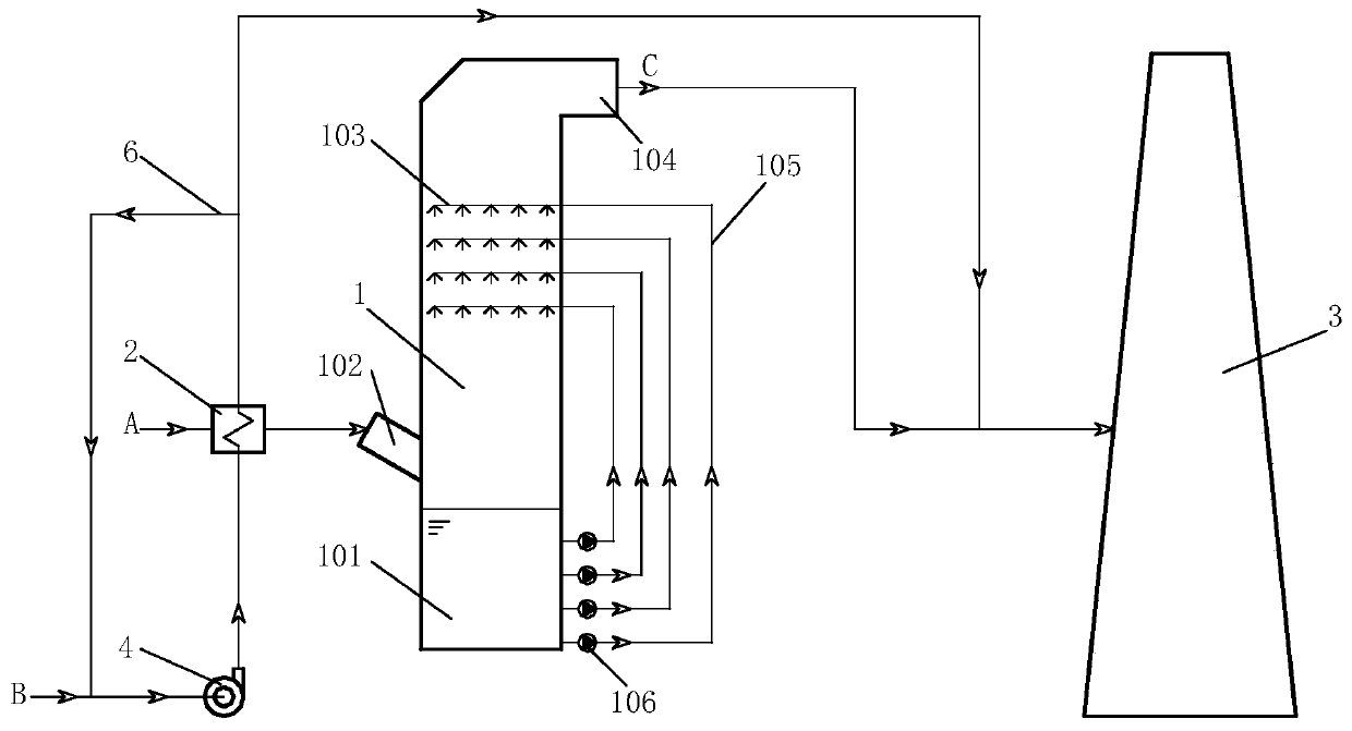
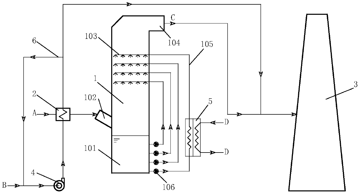
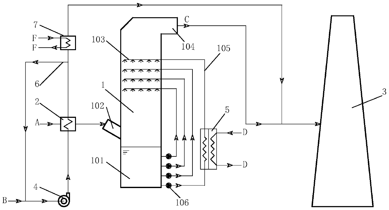
[0046] Such as figure 1 As shown, the present invention includes a desulfurization tower 1, a gas-gas heat exchanger 2, an air bypass 6, a chimney 3, and an air channel and a flue gas channel connecting the above-mentioned equipment, wherein the desulfurization tower includes a slurry tank 101 at the bottom, a slurry pipeline 105, Spray pipe 103, flue gas inlet 102, flue gas outlet 104 and other components, one end of the slurry pipe is connected with the slurry pool, and the other end is connected with the spray pipe located in the desulfurization tower, the slurry pipe is provided with a slurry pump 106, desulfurization The tower is equipped with a plurality of slurry pipelines 105, and the outlet positions of the slur...


PUM


Abstract

The invention relates to a wet desulphurization and smoke whiteness eliminating system, and relates to the fields of wet desulphurization technologies and smoke whiteness eliminating technologies. Thewet desulphurization and smoke whiteness eliminating system comprises an air-smoke heat exchanger, a desulphurization tower, a fan, a chimney, an air bypass, a smoke channel and an air channel, by means of hot air recirculation, air is preheated, then the air is used for exchanging heat with smoke, the smoke enters the desulphurization tower for desulphurization after being cooled, the heated airand the smoke subjected to desulphurization are mixed, temperature is elevated, the humidity is reduced, and the mixed air and smoke are discharged through the chimney, so that smoke whiteness eliminating is achieved. Compared with existing whiteness eliminating technology routes, the wet desulphurization and smoke whiteness eliminating system has the advantages that not only can the problems oflow-temperature corrosion, ash deposition and the like of smoke be effectively solved, but also system equipment is simple, the investment is little, whiteness eliminating modification is simple and easy to implement, and a whiteness eliminating effect is good, so that the wet desulphurization and smoke whiteness eliminating system has excellent economic benefits and social benefits.

Description

technical field [0001] The present invention relates to the application field of flue gas whitening, in particular to the application field of wet flue gas desulfurization technology flue gas whitening application, using air-gas heat exchange technology to solve low-temperature corrosion and dust accumulation through air backflow mode and air-gas partition wall heat exchanger To solve the problem of blockage, the residual heat of the recovered flue gas is used to raise the temperature and reduce the humidity of the flue gas after desulfurization, and then realize the process system of flue gas whitening. Background technique [0002] Most of the flue gas desulfurization in my country adopts wet flue gas desulfurization technology. The wet flue gas desulfurization technologies mainly include lime / limestone washing method, double alkali method, Wellman-Lord method, magnesium oxide method and ammonia method, among which lime The technology of limestone washing process is the mos...

Claims


Application Information

Patent Timeline
IPC IPC(8): B01D53/50B01D53/80B01D53/26F28C1/00F28D21/00
CPCB01D53/504B01D53/80B01D53/265F28C1/00F28D21/0003B01D2258/0283
Inventor 宋秉棠赵殿金
Owner TIANJIN HUASAIER HEAT TRANSFER EQUIP
Learn More