Flow adjusting device capable of changing plunger volume

A technology of flow regulating device and plunger, which is used in liquid variable capacity machinery, pump control, machine/engine, etc., and can solve the problems of large shock and vibration, high noise, unable to meet the application of pressure and large flow plunger reciprocating pump, etc. , to achieve the effect of improving life, small viscosity loss and smooth flow path

Active Publication Date: 2013-08-28
NINGBO HELI MECHANICAL PUMP CO LTD
View PDF9 Cites 7 Cited by
  • Summary
  • Abstract
  • Description
  • Claims
  • Application Information

AI Technical Summary

Problems solved by technology

[0004] These types of plunger reciprocating pumps and flow regulating devices can adjust the flow of independent outlets, but the first two have the disadvantages of large shock vibration and noise, and the third type has reduced vibration and noise, but it is only suitable for It is used in pumps with a pressure below 16MPa, and cannot meet the requirements of a pressure greater than 16MPa and a plunger reciprocating pump with a large flow rate.

Method used


Image

  • Flow adjusting device capable of changing plunger volume
  • Flow adjusting device capable of changing plunger volume
  • Flow adjusting device capable of changing plunger volume

Examples


Embodiment 1

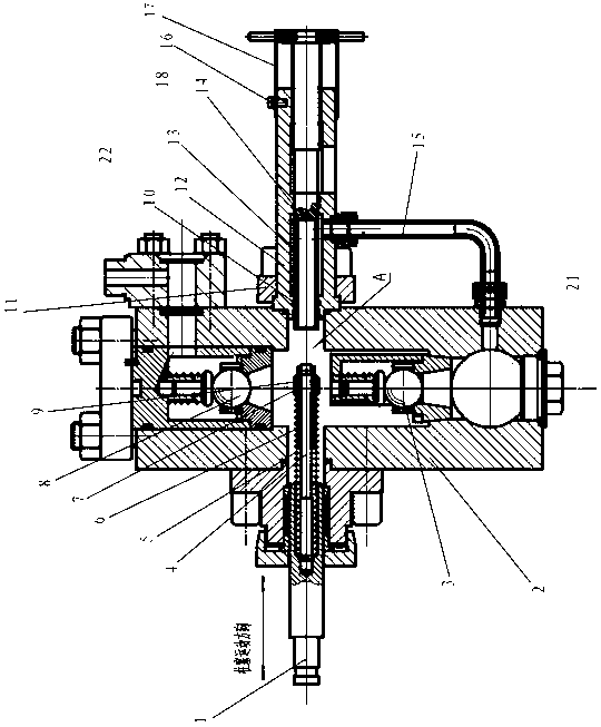
[0036] Specific as figure 1 , figure 2 , image 3 As shown, the plunger reciprocating pump mainly includes a pump body 2, a plunger 1 fitted in the plunger hole of the pump body, a suction valve group 3 and a discharge valve group 8 arranged in the pump body 2, wherein:

[0037] The pump body 2 is provided with an inlet 21 and an outlet 22, as well as a plunger hole for setting the plunger 1, and valve chambers for setting the suction valve group 3 and the discharge valve group 8 respectively, while the pump chamber A of the pump body is It is enclosed by a plunger, a suction valve group, a discharge valve group and the flow regulating device provided by the present invention.

[0038] The plunger 1 is slidingly fitted in the plunger hole of the pump body 2, and is driven to perform reciprocating linear motion in the plunger hole.

[0039] The flow regulating device provided by the present invention is installed on the pump body 2, located on the opposite side of the plung...

Embodiment 2

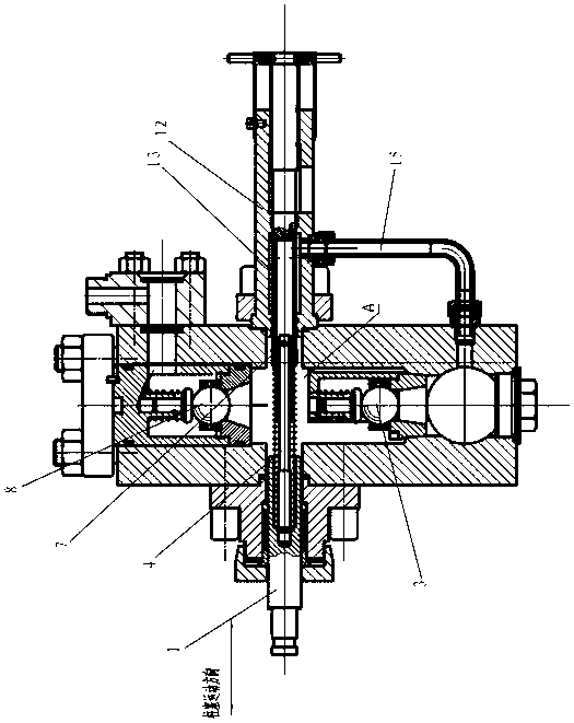
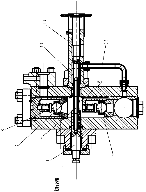
[0055] Specific as Figure 4 , Figure 5 with Image 6 Shown, different from embodiment one is:

[0056] The sealing of spool 7 and auxiliary plunger 4 is changed into the inner hole sealing of small piston 19 and adjusting rod 13, and all the other remain unchanged. That is: the inner hole of the spool 7 is directly slidably matched with the outer diameter of the auxiliary plunger 4, the guide seal 8 is canceled, the spring guide sleeve 6 is threaded at one end of the spool 7, and a coaxial step is added at the valve face end of the spool 7 hole. A pillow block is added to the end of the locking nut installed on the auxiliary plunger 4 for installing the small piston 19 . The small piston 9 is fixed on the end of the auxiliary plunger 4 with a lock nut. The through hole of the adjusting rod 13 must be finished and sealed with the outer diameter of the small piston 19 .

[0057] Its working principle is as follows: when the plunger 1 moves backwards for suction, the smal...


PUM


Abstract

The invention relates to a flow adjusting device capable of changing a plunger volume. The flow adjusting device is installed on a pump body (2) at the hydraulic end of a plunger reciprocating pump, located at one side, opposite to a plunger (1), of the plunger reciprocating pump, and is located inside a coaxial hole in the same central line of the plunger (1) of the plunger reciprocating pump. The flow adjusting device comprises an adjusting sleeve (12), an adjusting rod (13), and an auxiliary plunger (4) which is arranged on the end portion of the plunger of the plunger reciprocating pump coaxially. The flow adjusting device is characterized in that a plunger hole is formed inside the end portion of the plunger (1) of the plunger reciprocating pump, one end of the auxiliary plunger is arranged inside the plunger hole, the other end of the auxiliary plunger is installed inside a valve core (7) in a sliding, sealing and matching mode, the valve face of the valve core (7) can be matched with the valve face of the adjusting rod to realize the purpose of opening or closing of the valve face of the adjusting rod, and the auxiliary plunger (4) can move reciprocally under the driving of the plunger (1) and can move into and out of a through hole (131) inside the adjusting rod (13). The flow adjusting device is applicable to plunger reciprocating pumps with high pressure and large flow.

Description

technical field [0001] The invention relates to a flow regulating device for changing the volume of a plunger. The device can be installed on the liquid end pump body of a plunger reciprocating pump to realize the regulation of the discharge flow. Background technique [0002] The plunger reciprocating pump is a positive displacement pump. The output flow of the pump is related to the diameter of the plunger, the pump stroke and the pump speed (reciprocations per minute). Most of the existing plunger reciprocating pumps adopt changing the pump speed to adjust the flow. But this method is only applicable when a reciprocating pump has only one outlet. For a reciprocating pump with multiple cylinders and multiple outlets, if the flow rate of each independent outlet is required to be adjustable, the existing plunger reciprocating pump cannot meet the above requirements. [0003] In view of the above situation, the applicant of this case has developed two kinds of plunger recip...

Claims


Application Information

Patent Timeline
Patent Type & Authority Applications(China)
IPC IPC(8): F04B49/12
Inventor 陈明海李春生
Owner NINGBO HELI MECHANICAL PUMP CO LTD
Why Eureka
Try Eureka