
Indicating positions of and directions to battlefield entities in a soldier's head-mounted display

Active Publication Date: 2008-01-10
PRIMORDIAL
View PDF6 Cites 7 Cited by
  • Summary
  • Abstract
  • Description
  • Claims
  • Application Information

AI Technical Summary

Benefits of technology

[0023] Existing systems for differentiating friend from foe in combat suffer from a number of disadvantages. Specifically, existing systems:
[0024] a. Delay firing decisions. Existing systems require that a soldier obtain line-of-sight access and initiate an identification sequence before determining whether a unit is a friend or foe. As a result, soldiers need to wait for units to come into view and to manually perform an interrogation before making a firing decision.
[0025] b. Fail to eliminate friendly fire. A soldier who improperly aims his or her interrogator or fires in the heat of battle before initiating an identification sequence may injure or kill fellow soldiers.
[0026] c. Fail to identify unknown units as friend, foe, or neutral. Although existing sy

Problems solved by technology

A soldier who improperly aims his or her interrogator or fires in the heat of battle before initiating an identification sequence may injure or kill fellow soldiers.
Although existing systems differentiate friendly units from unknown units, they cannot further classify unknown units as friend, foe, or neutral.
As a result, soldiers are susceptible to surprise attack as enemy units suddenly come into view.
Unfortunately, a visible enemy unit may launch an attack before a friendly unit can initiate the identification sequence.
As a result, existing systems place soldiers at risk of attack while they differentiate units.
As a result, existing systems leave soldiers vulnerable to attack by obscured or distant enemies.
The heavy load limits a soldier's range and maneuverability.

Method used


Image

  • Indicating positions of and directions to battlefield entities in a soldier's head-mounted display
  • Indicating positions of and directions to battlefield entities in a soldier's head-mounted display
  • Indicating positions of and directions to battlefield entities in a soldier's head-mounted display

Examples


Embodiment Construction

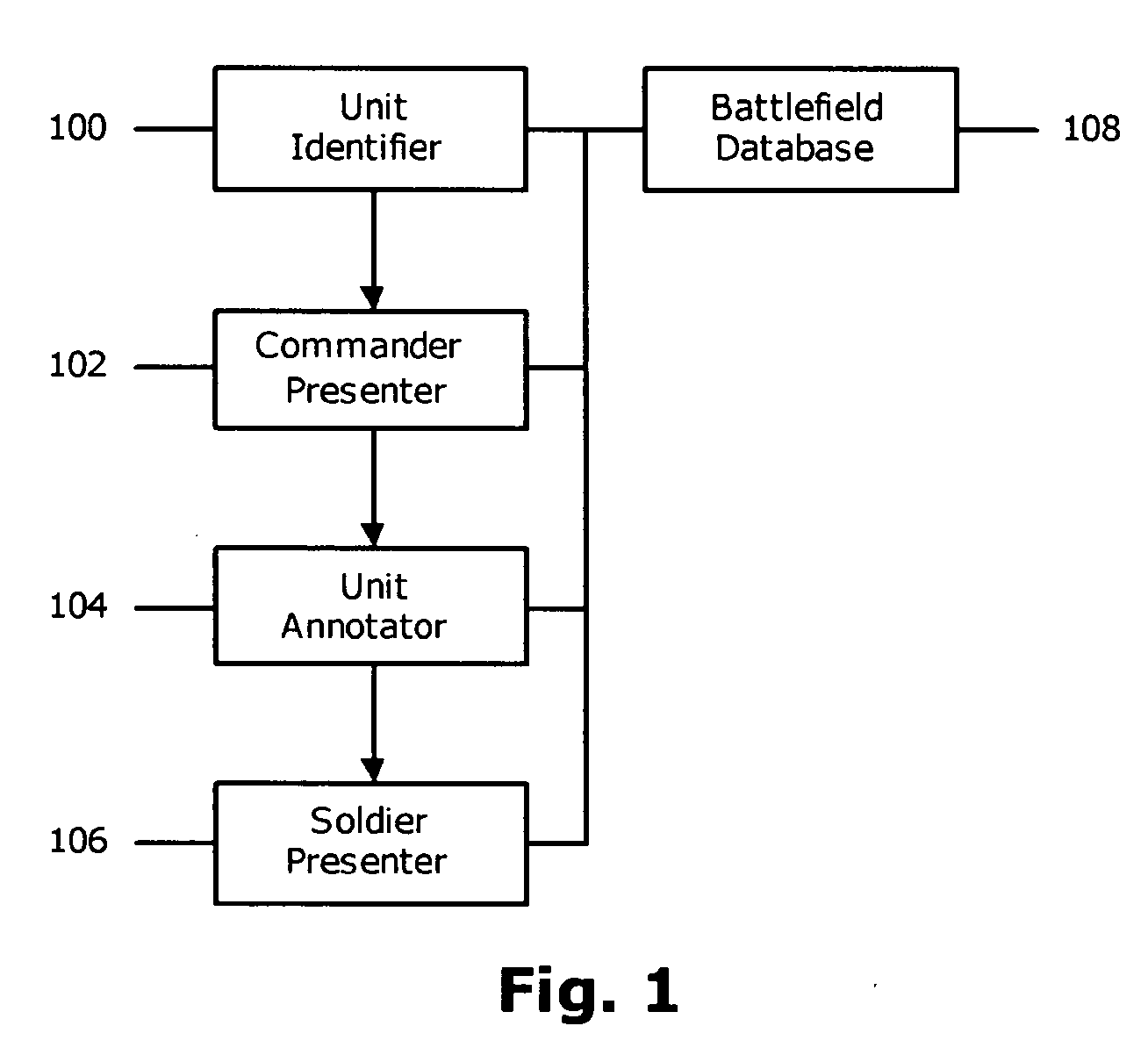
[0059]FIG. 1 shows a preferred embodiment of the present invention. The processing is performed by four components. The Unit Identifier 100 associates objects detected in aerial imagery with soldiers on the battlefield. The Commander Presenter 102 displays the aerial imagery and overlays symbols representing the soldiers. The Unit Annotator 104 enables commanders to tag soldiers as friend, foe, or neutral. The Soldier Presenter 106 identifies units that appear in a soldier's head-mounted display.

[0060] Each of the components has access to the Battlefield Database 108. The Battlefield Database 108 contains the position, name, orientation, rank, and type of each soldier. In addition, the Battlefield Database 108 contains aerial imagery of the battlefield and scope video captured by weapon-mounted cameras carried by soldiers. To perform line-of-sight analysis, the Battlefield Database 108 includes a standard Geographic Information System (GIS) such as MapInfo™ by ESRI, Inc. of Redland...


PUM


Abstract

A computer-implemented method for indicating positions of and directions to battlefield entities in a soldier's head-mounted display using annotated arrows which indicate units both in and out of the soldier's field of view. The method includes a Unit Identifier (100) for associating units in aerial imagery with soldiers on the battlefield, a Commander Presenter (102) for presenting the aerial imagery and unit positions to a commander, a Unit Annotator (104) for enabling commanders to identify unknown units, and a Soldier Presenter (106) for identifying and labeling units that appear in a soldier's head-mounted display.

Description

CROSS-REFERENCE TO RELATED APPLICATIONS [0001] This application is a continuation of U.S. Ser. No. 10 / 249,761, filed 2003 May 6, now allowed, the entire disclosure of which is incorporated by reference herein.BACKGROUND OF INVENTION [0002] 1. Field of Invention [0003] This invention relates to image analysis, specifically to identifying friendly and enemy units in a soldier's head-mounted display. [0004] 2. Discussion of the Background [0005] In September 2000, the U.S. Army performed the first operational test of the Land Warrior soldier system. The system connects soldiers on the battlefield via a wireless network. In addition, each Land Warrior carries a computer connected to a GPS receiver, scope video camera, and head-mounted display. The head-mounted display presents video from the scope camera attached to the soldier's weapon. As a result, the soldier can point his or her gun around a corner to assess enemy activity while minimizing exposure to attack. [0006] A Land Warrior's...

Claims


Application Information

Patent Timeline
IPC IPC(8): G06K9/00G06V20/13
CPCF41G3/02F41G3/16F41G3/225G02B27/017G06K9/0063A63F2300/307G02B2027/0141G02B2027/0138G02B2027/014A63F13/10G06F3/012G06V20/13A63F13/5378
Inventor MILBERT, RANDY L.
Owner PRIMORDIAL
Learn More