Complicated stable sound field sound pressure testing device

A pressure testing and stable technology, applied in the direction of measuring devices, measuring ultrasonic/sonic/infrasonic waves, instruments, etc., can solve problems such as troublesome debugging and installation, inability to complete on-site, and no detailed description, etc., to achieve convenient debugging, reliable test data, The effect of reducing human error

Active Publication Date: 2016-05-18
柳州市展虹科技有限公司 +1
View PDF6 Cites 14 Cited by
  • Summary
  • Abstract
  • Description
  • Claims
  • Application Information

AI Technical Summary

Problems solved by technology

[0002] Near-field acoustic holography technology is the frontier of acoustic research in recent years. Near-field acoustic holography (NAH) can be used to identify and locate sound sources more accurately. Using this technology, near-field sound field reconstruction and visualization can be realized. Therefore, NAH Technical research is of great significance for suppressing noise pollution. The key to NAH technology is how to measure the sound pressure distribution on the holographic surface. However, the existing test devices are relatively cumbersome, debugging and installation are very troublesome, and the workload is very heavy. It requires a lot of manpower and material resources, and the test results generally cannot be completed on site, and need to be returned to the laboratory for processing. Therefore, it is necessary to invent a small, lightweight new sound pressure test device, which is controlled by the corresponding intelligent control system ( Not the key point of the present invention, do not elaborate here, see under the control of the intelligent control system of this device that applies for on the same day as the present invention), can automatic debugging, automatic correction, automatic test, automatic calculation result, to reduce a large amount of manpower and material resources , to reduce the labor intensity of people, and at the same time, it is especially suitable for on-site operations with large complex and stable sound fields

Method used


Image

  • Complicated stable sound field sound pressure testing device
  • Complicated stable sound field sound pressure testing device
  • Complicated stable sound field sound pressure testing device

Examples


Embodiment Construction

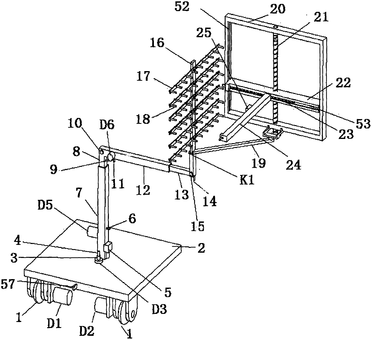
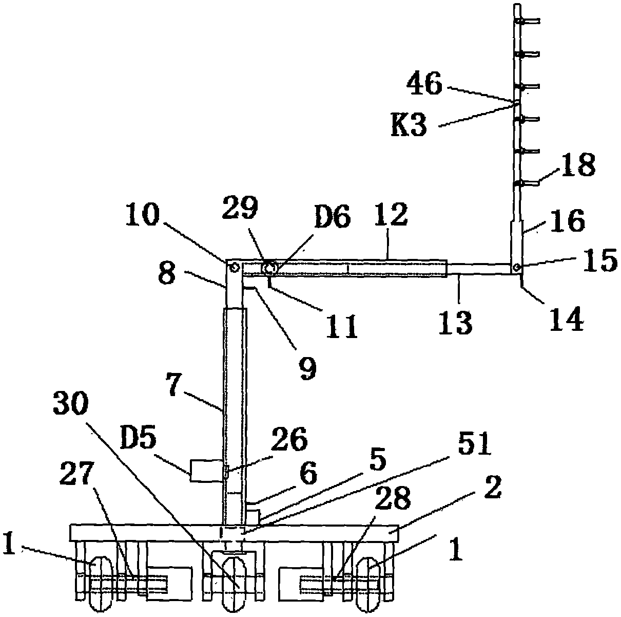
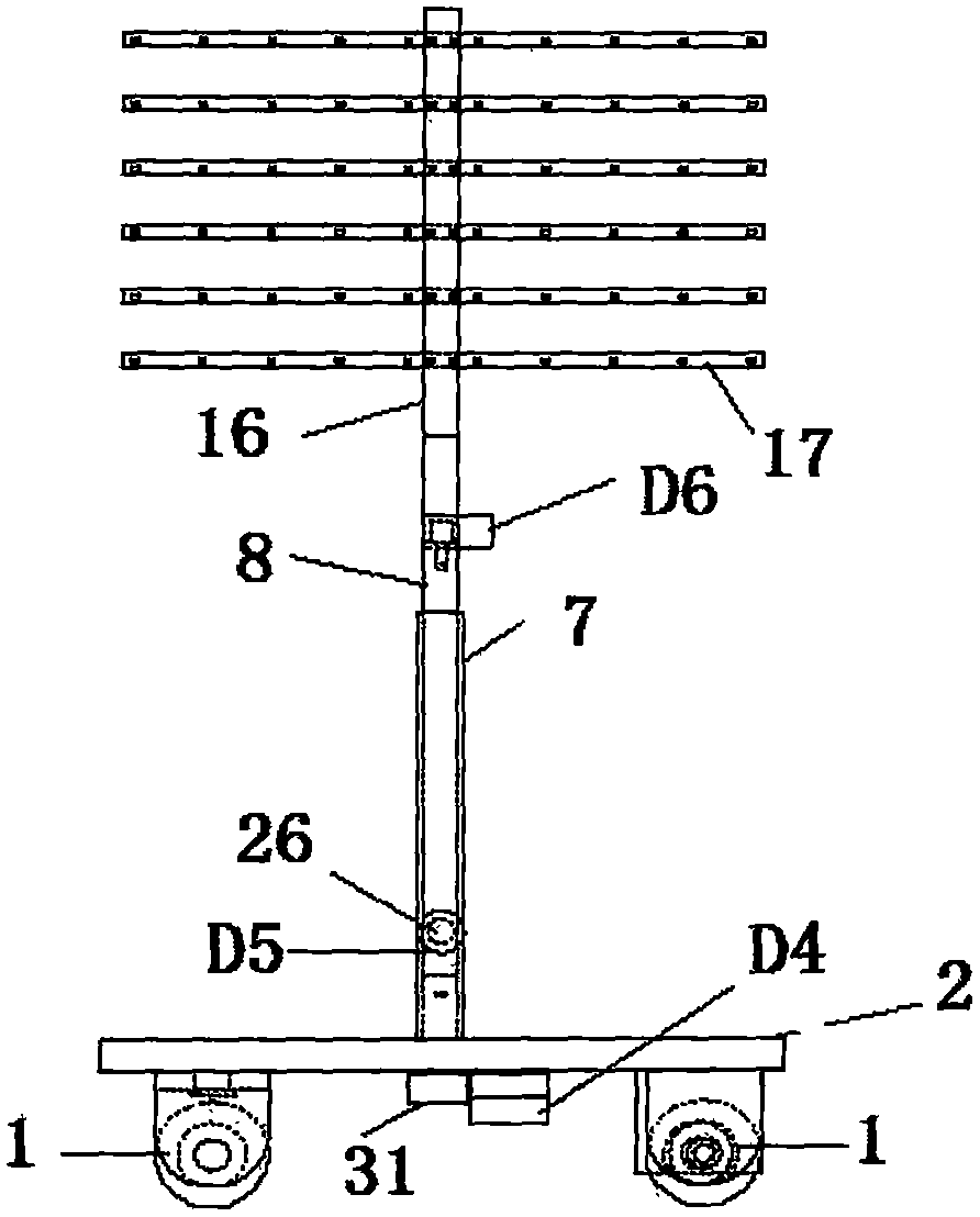
[0031] Such as Figure 1 to Figure 10 As shown, the present invention is a complex and stable sound field sound pressure testing device, which includes a driving mechanism I for the movement of the whole device, an acoustic probe array lifting and rotating driving mechanism II, an acoustic probe array telescopic driving mechanism III, an acoustic probe array IV, an acoustic Probe array test channel calibration drive mechanism V, sound source reference position measurement column VI, point sound source standard sound wave generator VII. The driving mechanism 1 of described whole device motion comprises base 2, base 2 is provided with driving wheel 1 and universal wheel 30, is provided with electric control box 5 on base 2, and electric control box 5 is used for placing control circuit board, and base 2. The center is connected with the chute I7 ​​of the acoustic probe array lifting and rotating drive mechanism II through the bearing sleeve VIII51. The acoustic probe array lifti...


PUM


Abstract

The invention discloses a complicated stable sound field sound pressure testing device relating to an acoustic testing device. The testing device comprises a driving mechanism I used for driving the whole device to move, an acoustic probe array elevating and rotating driving mechanism II, an acoustic probe array telescopic driving mechanism III, an acoustic probe array IV, an acoustic probe array testing channel correcting driving mechanism V, a sound source reference position measuring column VI, and a point sound source standard sound wave generator VII. The complicated stable sound field sound pressure testing device is advantageous in that the testing device is small and light; the installation and the debugging of the testing device are relatively simple; during the measurement, the labor force and the material force can be greatly reduced, and the labor intensity can be reduced, and in addition, the precision of the measurement data can be increased, and at the same time, the testing device is especially suitable for the on-site operation of the large-scale complicated stable sound field.

Description

technical field [0001] The invention relates to an acoustic testing device, in particular to a new device for sound pressure testing of complex and stable sound fields. Background technique [0002] Near-field acoustic holography technology is the frontier of acoustic research in recent years. Near-field acoustic holography (NAH) can be used to identify and locate sound sources more accurately. Using this technology, near-field sound field reconstruction and visualization can be realized. Therefore, NAH Technical research is of great significance for suppressing noise pollution. The key to NAH technology is how to measure the sound pressure distribution on the holographic surface. However, the existing test devices are relatively cumbersome, debugging and installation are very troublesome, and the workload is very heavy. It requires a lot of manpower and material resources, and the test results generally cannot be completed on site, and need to be returned to the laboratory ...

Claims


Application Information

Patent Timeline
Patent Type & Authority Applications(China)
IPC IPC(8): G01H17/00
CPCG01H17/00
Inventor 伍松李俞霖向宇
Owner 柳州市展虹科技有限公司
Why Eureka
Try Eureka