Dynamic target tracking accuracy test device for photoelectric detection equipment

A photoelectric detection and dynamic target technology, applied in the direction of radio wave measurement systems, instruments, etc., can solve the problems of limited installation space, small tracking range, and poor versatility, and achieve the effect of large installation space, small volume limit, and good versatility

Active Publication Date: 2016-05-18
LUOYANG INST OF ELECTRO OPTICAL EQUIP OF AVIC
View PDF5 Cites 15 Cited by
  • Summary
  • Abstract
  • Description
  • Claims
  • Application Information

AI Technical Summary

Problems solved by technology

[0003] When the above-mentioned target simulator is used in practice, since the photoelectric detection equipment to be tested is directly installed on the base, and the installation space in the center of the base is limited, it is not convenient for the installation of large-scale photoelectric detection equipment.
Moreover, photoelectric detection systems with different installation interfaces require different fixtures for installation and fixation. Therefore, it is extremely inconvenient to install and disassemble the system under test, and the versatility is poor.
Moreover, since the rotating frame is arranged on the base, the rotating range of the frame with the vertical track is mostly limited to a certain interval, and the tracking range is small

Method used


Image

  • Dynamic target tracking accuracy test device for photoelectric detection equipment
  • Dynamic target tracking accuracy test device for photoelectric detection equipment
  • Dynamic target tracking accuracy test device for photoelectric detection equipment

Examples


Embodiment Construction

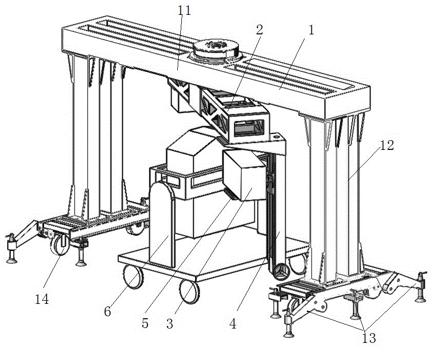
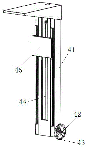
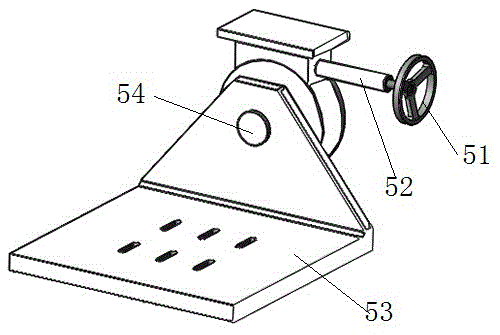
[0021] Such as Figure 1 to Figure 3 Shown, a kind of embodiment of photoelectric detection equipment dynamic target tracking precision test device, the test device in this embodiment comprises portal frame 1, and portal frame 1 has two vertical legs 12 of upper beam 11 and two ends, in On the upper beam 11, the position corresponding to the photoelectric detection device 6 to be tested is provided with a central rotating shaft extending in the up and down direction, and a cantilever beam 2 is installed coaxially rotating at the position of the central rotating shaft, and the cantilever beam 2 is far away from the central rotating shaft. The target source 3 for simulating the target tracked by the photoelectric detection equipment to be tested is installed at the far end of the position, and the cantilever beam 2 can carry the target source 3 in the range of the portal frame 1 to make a circumferential revolution. The cantilever beam 2 here Driven by a rotating motor, the rota...


PUM


Abstract

The invention relates to a dynamic target tracking accuracy test device for photoelectric detection equipment. The device comprises a target source arranged to orient towards to-be-tested photoelectric detection equipment, a door-shaped framework with an upper crossbeam. The part of the upper crossbeam, corresponding to the to-be-tested photoelectric detection equipment, is provided with a central rotation shaft capable of extending along the up-and-down direction. A cantilever beam is rotatably assembled at the coaxial position of the rotation shaft. The target source is arranged at the far-end part of the cantilever beam that is far away from the central rotation shaft. The cantilever beam is capable of driving the target source to conduct the circumferential revolution within the range of the door-shaped framework. During usage, the to-be-tested photoelectric detection equipment is placed below the lower crossbeam of the door-shaped framework, so that a large installation space is easily provided. The device has little limitation on the size of the to-be-tested photoelectric detection equipment, and good in generality. Meanwhile, the target source is driven by the cantilever beam to conduct the circumferential revolution. Therefore, a largest target tracking range is provided for the to-be-tested photoelectric detection equipment.

Description

technical field [0001] The invention relates to a dynamic target tracking accuracy testing device for photoelectric detection equipment. Background technique [0002] The existing photoelectric detection system dynamic tracking accuracy test usually uses a target turntable, and the system under test must be installed in the center of the turntable frame, such as the target simulation for the photoelectric radar dynamic performance test disclosed in the Chinese utility model patent with the authorized announcement number CN201464648U The device includes a base for fixedly placing the photoelectric radar to be tested, a frame with a vertical track is rotatably mounted on the base, a slide plate is slidably mounted on the vertical track, and a target source for simulating the target is arranged on the slide plate. The target source and the slide plate are hinged so that the target source is always aligned with the center of the photoelectric radar scanning mirror. The target si...

Claims


Application Information

Patent Timeline
Patent Type & Authority Applications(China)
IPC IPC(8): G01S7/497
CPCG01S7/497
Inventor 岳卫兵毛鑫
Owner LUOYANG INST OF ELECTRO OPTICAL EQUIP OF AVIC
Why Eureka
Try Eureka