Electric quantity wireless metering system

A metering system and wireless technology, applied in the field of electric power wireless metering system, can solve the problems of hidden safety hazards, troublesome household entry, and high management costs, and achieve real-time monitoring, prevention of arrears and electricity theft, and low cost.

Inactive Publication Date: 2016-05-18
QINGDAO XINYIFA IND & TRADE
0 Cites 1 Cited by

AI-Extracted Technical Summary

Problems solved by technology

There are many disadvantages in the traditional meter reading method, such as the trouble of entering the house, high mana...

Method used

(1) 32 ARM7TDMI-S cores, it has the characteristics of high performance and low power consumption, owing to have used pipeline technology, all parts of processing and storage system can work continuously, can finish collector and concentrate efficiently Data processing, sending and receiving work of the device;...

Abstract

The invention relates to an electric quantity wireless metering system which includes a monitoring center and a concentrator arranged at a data collection point. A plurality of computers are connected to the monitoring center. A GPRS module is connected to the monitoring center for receiving information. A GPRS module arranged on the concentrator at the data collection point is used for sending information. A collector is connected to the concentrator and is connected to a plurality of user electricity meters. The system achieves wireless collection of electricity consumption information of users, and achieves online pre-paying and real-time monitoring on electricity consumption situation through statistical processing on data, thereby effectively preventing arrears and electricity stealing and the like. The monitoring center publishes the electricity consumption information of the users on Web through Internet, so that users can query the information conveniently, thereby effectively avoiding dispute. The system is low in cost, and is a high-effective and reliable automatic meter reading system.

Application Domain

Transmission systems

Technology Topic

Statistical processingAutomatic meter reading +8

Image

  • Electric quantity wireless metering system
  • Electric quantity wireless metering system
  • Electric quantity wireless metering system

Examples

  • Experimental program(1)

Example Embodiment

[0015] Specific embodiments of the present invention will be described below in conjunction with the accompanying drawings, so as to better understand the present invention.
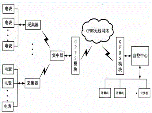
[0016] like figure 1 The shown wireless power metering system includes a monitoring center and a concentrator arranged at the data collection point, wherein the monitoring center is connected with multiple computers, and the monitoring center is connected with a GPRS module for receiving information; The concentrator is provided with a GRPS module for sending information, the concentrator is connected to a collector, and the collector is connected to multiple user electric meters.
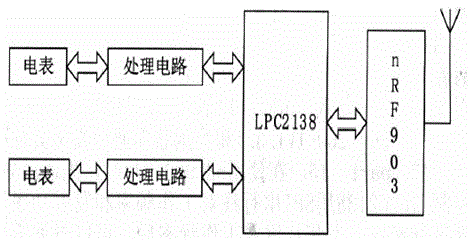
[0017] like figure 2 The collector module shown includes an LPC2138 chip, an nRF903 wireless module and multiple processing circuits are connected to the LPC2138 chip, and a user electric meter is connected to each processing circuit.
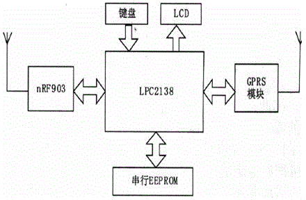
[0018] like image 3 The concentrator module shown includes the LPC2138 chip, and the LPC2138 chip is connected with a GPRS module, nRF903 module, keyboard, LCD display and serial EEPROM.
[0019] Both GPRS module and nRF903 module are equipped with wireless antennas.
[0020] In the above inventive device, the data collector regularly collects the data of the electric meter of the user through the LPC2138 serial port, and stores it in the memory of the collector. When the concentrator sends an instruction, the collector can perform corresponding operations according to the instruction content, and send the historical power data of the user's electric meter and the current electric meter data to the concentrator through the radio frequency module, and store them after being processed by the concentrator. The user can use the keyboard and LCD query and display. The concentrator transmits the collected data to the GPRS module through the RS-232 interface, and then sends it to the monitoring center of the power company through the GPRS wireless network. The monitoring center performs statistical processing on the electricity consumption data, realizes the automatic measurement and collection of data, automatic data transmission and remote automatic monitoring of the user's electric meter. At the same time, the remote control of the metering equipment is realized through the two-way system of GPRS, and the control operations such as parameter adjustment and switching are performed.
[0021] Through this system, users can prepay through online banking, and the monitoring center deducts the electricity consumption fee every month. If the balance is insufficient, it will send a control signal to the user's electric meter through this system to perform operations such as power failure. In addition, the monitoring center can publish the Web through the local area network, and the user can query the electricity consumption information through the Internet.
[0022] The hardware of this system can be divided into two modules: collector module and concentrator module. Among them, there are many microcontrollers, wireless transceiver chips and GPRS modules to choose from for collectors and concentrators. This system is based on ARM microcontrollers LPC2138, nRF903 and MC55.
[0023] 1. ARM microcontroller LPC2138:
[0024] In order to make the system stable and reliable, and meet the design requirements of low power consumption and intelligence, this system selects LPC2138 as the core controller of the collector and concentrator. LPC2138 is a 32-bit ARM7TDMI2STMCPU microcontroller that supports real-time emulation and embedded tracking. Its main features are:
[0025] (1) 32-bit ARM7TDMI-S core, which has the characteristics of high performance and low power consumption. Due to the use of pipeline technology, all parts of the processing and storage system can work continuously, and can efficiently complete the data of the collector and concentrator Processing, sending and receiving work;
[0026] (2) 32kB on-chip static RAM and 512kB on-chip Flash program memory avoid LPC2138 external memory expansion, simplify the circuit, and improve the operating speed. programming and storage for non-volatile programs;
[0027] (3) Two 8-way 10-bit A/D converters provide a total of 16 analog inputs, and the conversion time of each channel is as low as 2.44μs. 2 32-bit timer/counters (with 4-way capture and 4-way comparison channels), PWM unit (6-way output) and watchdog;
[0028] (4) Multiple serial interfaces, including 2 16C550 industry standard UARTs, 2 high-speed 12C interfaces (400kb/s), SPITM and SSP with buffering and variable data length functions, including up to 47 general-purpose I/ O port (can withstand 5V voltage), to meet the requirements of connecting a large number of meters;
[0029] (5) Up to 9 edge or level-triggered external interrupt pins, through the on-chip PLL (100μs setup time), can achieve a maximum CPU operating frequency of 60MHz;
[0030] (6) Single power supply, with power-on reset (POR) and brownout detection (BOD) circuits, CPU operating voltage range: 3.0 ~ 3.6V (3.13v±10), can share a power supply with nRF903.
[0031] 2. Collector module:
[0032] Collector modules such as figure 2 As shown, the collector and the meter are connected through a serial interface, and the collector and the concentrator are connected through a wireless transceiver module. The collector regularly collects the meter readings and stores the data in the on-chip static RAM; when the collector receives the command from the concentrator, the collector either transmits the historically stored power data and current meter readings, or performs operations such as time adjustment.
[0033] 3. Concentrator module:
[0034] Concentrator modules such as image 3 As shown, the microcontroller sends and receives data through the wireless transceiver chip nRF903. When the data is received from nRF903, it is processed and stored in the serial EEPROM, and the user's power consumption data can be viewed through the display. At the same time, LPC2138 is interconnected with GPRS module MC55, and communicates with the monitoring center through MC55 and GPRS network.
[0035] The system can be roughly divided into three levels: user electric meters with communication interfaces, concentrators (or collectors) for collecting and managing several nearby household electric meters, and management centers for electric industry authorities. The three levels are connected in some way for data communication. Among various forms of meter reading systems, the main difference lies in the different inter-level communication methods adopted. After discussing and comparing various communication methods, the author proposes a cost-effective solution, which is to use an automatic meter reading system based on serial interface, radio frequency module and GPRS. Among them, the communication between the user electric meter and the collector is through the serial interface, the communication between the collector and the concentrator is through the radio frequency module, and the communication between the concentrator and the monitoring center is through GPRS.
[0036] The process of the system is: the collector regularly collects data from the meter and stores it in the memory; the concentrator collects data from the collector at the end of each month and stores it after processing; the monitoring center collects data from the user's meter at the beginning of each month and stores it after statistical processing up for staff and user queries. At the same time, this system can realize real-time monitoring. The specific process is that the monitoring center sends query or control commands to the concentrator through the GPRS network. The device controls the meter to realize real-time monitoring.
[0037] The above description is a preferred embodiment of the present invention, and it should be pointed out that for those skilled in the art, without departing from the principle of the present invention, some improvements and modifications can also be made, and these improvements and modifications are also considered Be the protection scope of the present invention.

PUM

no PUM

Description & Claims & Application Information

We can also present the details of the Description, Claims and Application information to help users get a comprehensive understanding of the technical details of the patent, such as background art, summary of invention, brief description of drawings, description of embodiments, and other original content. On the other hand, users can also determine the specific scope of protection of the technology through the list of claims; as well as understand the changes in the life cycle of the technology with the presentation of the patent timeline. Login to view more.

Similar technology patents

Data processing method and device

PendingCN111428963ARealize real-time monitoring
Owner:BEIKE TECH CO LTD

Indoor loading device for breaking hot dry rock through microwave irradiation in simulated geothermal environment

PendingCN112834340ARealize real-time monitoring
Owner:SOUTHWEST PETROLEUM UNIV

Rocking arm with signal output

InactiveCN102995997ARealize real-time monitoringSimple structure
Owner:SUZHOU FUERDA TECH CO LTD

Solid-liquid interface photoelectric detection sensor, detection device and detection method

PendingCN114152312ARealize real-time monitoring
Owner:NANJING UNIV OF AERONAUTICS & ASTRONAUTICS

New energy automobile brake system

PendingCN114852037ARealize real-time monitoringDeepen understanding
Owner:SONGUO MOTORS CO LTD

Classification and recommendation of technical efficacy words

  • Realize real-time monitoring

Intellectualized monitoring method for industrial park waste water discharge pollutant

InactiveCN101302042ARealize real-time monitoringEnsure safe and reliable operation
Owner:SOUTHEAST UNIV +1

Radiotherapy system and real-time monitoring method thereof

InactiveCN103845816ARealize real-time monitoringAvoid extra dose deposition
Owner:SHANGHAI UNITED IMAGING HEALTHCARE

Asphalt mixing station monitoring and management system based on IoT technology

InactiveCN105700442ARealize real-time monitoringImprove productivity and quality
Owner:CHANGAN UNIV

A method for fault diagnosis of on-line monitor equipment of transmission line

ActiveCN109472097Acomplex structureRealize real-time monitoring
Owner:国网湖北省电力有限公司黄石供电公司 +1

Precision monitoring system for time synchronization of power equipment

InactiveCN106647227ARealize real-time monitoringHigh measurement accuracy
Owner:STATE GRID JIANGXI ELECTRIC POWER CO +1
Why Eureka
Try Eureka