
Cable protection device

A technology of cable protection and protection device, applied in electrical components and other directions, can solve the problems of electric disconnection during construction, affecting the civilized construction image of the construction site, damage to the cable protective layer, etc., to improve safety, improve the level of civilized construction, and beautify the layout.

Inactive Publication Date: 2016-05-18
CHINA NUCLEAR IND 22ND CONSTR
View PDF0 Cites 4 Cited by
  • Summary
  • Abstract
  • Description
  • Claims
  • Application Information

AI Technical Summary

Problems solved by technology

[0003] 1. Aerial layout: Generally, iron wires are used to directly bind the cables and then hang them or directly place the cables on the steel pipe scaffolding, which may easily cause damage to the cable protective layer, cause electrical safety accidents, and at the same time affect the civilized construction image of the construction site;
[0004] 2. Laying along the ground: Generally, the construction power cables are laid directly on the ground surface along the designated lines, which affects the traffic on the construction site.

Method used


Image

  • Cable protection device
  • Cable protection device
  • Cable protection device

Examples


Embodiment Construction

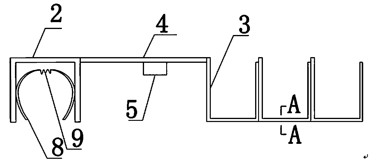
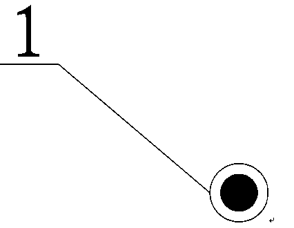
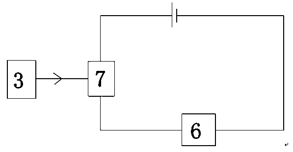
[0015] like figure 1 , figure 2 Among them, a cable protection device includes a hook, an electric leakage alarm device 5, and an insulating sheath 1 covered on the hook. The insulating sheath 1 is made of an insulating rubber or plastic hose. The hook includes a fixed opening with an opening downward. U-shaped groove 2, three cable U-shaped grooves 3 with upward openings, and elastic fixing clips are arranged in the U-shaped grooves fixing U-shaped groove 2, and the elastic fixing clips include two clamping arms 8, spring connectors 9, two clamping arms 8 are respectively movable and fixed on the inner wall of the fixed U-shaped groove 2, and the two ends of the spring connector 9 are respectively connected with a clamp arm 8, and the adjacent cable U-shaped groove 3 is directly fixed, and the fixed U-shaped groove 2 and the cable U-shaped groove 3 pass through The connecting rod 4 is connected; the connecting rod 4 can be stretched;

[0016] like image 3 , the leakage a...


PUM


Abstract

A cable protection device comprises a hanging hook and an insulating sheath which sleeves the hanging hook. The hanging hook comprises a fixed U-shaped groove with a downward opening and multiple cable U-shaped grooves each with an upward opening. The U-shaped groove of the fixed U-shaped groove is internally provided with an elastic fixing clamp. The adjacent cable U-shaped grooves are directly fixed. The fixed U-shaped groove and the cable U-shaped grooves are connected through a connecting rod, and the connecting rod is stretchable. The cable protection device is advantaged in that the cable protection device has a simple structure and improves the electricity safety in the construction field.

Description

technical field [0001] The invention relates to an auxiliary device for cable erection, which is a cable protection device. Background technique [0002] The existing protection methods for construction electric cables generally adopt overhead laying or laying along the ground, and the disadvantages are: [0003] 1. Aerial layout: Generally, iron wires are used to directly bind the cables and then hang them or directly place the cables on the steel pipe scaffolding, which may easily cause damage to the cable protective layer, cause electrical safety accidents, and at the same time affect the civilized construction image of the construction site; [0004] 2. Laying along the ground: Generally, the construction power cables are laid directly on the ground surface along the designated lines, which affects the traffic on the construction site. Contents of the invention [0005] In view of the above technical problems, the present invention provides a cable protection device w...

Claims


Application Information

Patent Timeline
Patent Type & Authority Applications(China)
IPC IPC(8): H02G3/04
Inventor 谢利平
Owner CHINA NUCLEAR IND 22ND CONSTR
Learn More