AI technical title is built by Patsnap AI team. It summarizes the technical point description of the patent document.
A spiral, hole-forming technology, applied in planting methods, excavation/covering trenches, plant protection covers, etc., can solve problems such as unfavorable crop growth, high power consumption, and large drill bit friction resistance, and achieves favorable plant growth. , The effect of reducing the cost of use and improving work efficiency
Inactive Publication Date: 2017-11-28
SOUTHWEST UNIV
View PDF3 Cites 0 Cited by
Summary
Abstract
Description
Claims
Application Information
AI Technical Summary
This helps you quickly interpret patents by identifying the three key elements:
Problems solved by technology
Method used
Benefits of technology
Problems solved by technology
[0003] At present, the nest-making machines widely used in northern operations are large in size and supporting power. Due to geographical constraints and different soil characteristics, these machines are not suitable for operations in hilly and mountainous areas in the south.
Therefore, the process of making nests and forming holes in agricultural production in hilly and mountainous areas of our country mainly relies on manual work, which is labor-intensive and inefficient.
[0004] In recent years, small motorized drill bit caving machines have also been used to make nests, but the depth of the caves is not easy to control, and the walls of the holes are prone to collapse, resulting in poor quality of the caves.
[0005] Patent application number 201320241126.9 "Planting machine for planting seedling well pits", patent application number 201420023267.8 "A shoulder-mounted tobacco seedling transplanting and punching machine", patent application number 201320222770.1 "Handheld electric flue-cured tobacco well cellar transplanting and punching ", etc., the hole-forming heads used are all cones, relying on their high-speed rotation to squeeze the holes, resulting in soil compaction on the walls of the holes and being too smooth, which is not conducive to the growth of crops; at the same time, the drill bits have high frictional resistance and are easy to wear. and high power consumption
Method used
Image
Click on the blue label to locate the original text in one second.
Reading with bidirectional positioning of images and text.
Examples
Embodiment Construction
[0024] The specific embodiments of the present invention will be further described in detail below in conjunction with the accompanying drawings, but the present invention is not limited to these embodiments, and any improvement or substitution on the basic spirit of the embodiments still belongs to the scope of protection of the claims of the present invention.
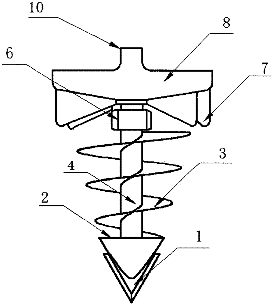
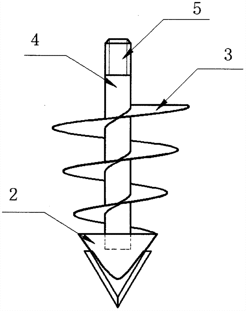
[0025] Such as figure 1 As shown, a conical spiral cavitation device includes a cavitation assembly and a coupling assembly. The cavitation assembly is composed of a central shaft 4, a conical spiral blade 3, a cavitation cone 2 and a reaming knife 1. The central shaft 4 is a hollow shaft, one end of which has an external thread 5, and the other end is connected with the hole-forming cone 2; the frustum-shaped helical blade 3 is in the shape of an inverted frustum, and is sleeved on the central shaft 4 through its inner hole, and is fixed by welding so that it is connected with the The central axis 4 and the hole-for...
PUM
Abstract
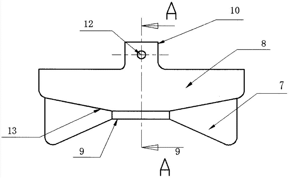
The invention relates to the technical field of agricultural machines, and discloses a conical spiral cavitating device. The conical spiral cavitating device comprises a cavitating assembly and a connecting assembly and is characterized in that the cavitating assembly is composed of a center shaft, a circular-truncated-cone-shaped spiral blade, a cavitating cone and a reaming cutter, an external thread is arranged at one end of the center shaft, the other end of the center shaft is connected with the cavitating cone, the circular-truncated-cone-shaped spiral blade is arranged on the center shaft in a sleeving mode through an inner hole and is fixedly welded, and then the circular-truncated-cone-shaped spiral blade, the center shaft and the cavitating cone are connected into a whole; the connecting assembly is composed of a circular-truncated-cone-shaped flange plate, a flange plate outer boss, a flange plate inner boss and breast boards, the face, provided with the outer boss, of the circular-truncated-cone-shaped flange plate is a plane, the face, provided with the inner boss, of the circular-truncated-cone-shaped flange plate is a conical surface, and the four breast boards are uniformly distributed on the conical surface in the radial direction. The conical spiral cavitating device has the advantages that the cavity hole wall is not prone to collapsing, cavitating quality is high, by means of the circular-truncated-cone-shaped spiral blade, work friction resistance is small, power consumption is low, the cavitating assembly which is a quick-wear part is easy to disassemble, and therefore cost of a whole machine is greatly reduced.
Description
technical field [0001] The invention relates to the technical field of agricultural machinery, in particular to a conical spiral hole forming device. Background technique [0002] In agricultural production processes such as sowing, transplanting, and fertilization, making nests and forming holes is a prerequisite for operations. This type of nesting and forming holes is characterized by small apertures, generally less than 10cm, and a depth of less than 20cm. The quality of the holes is high. [0003] At present, the nest-forming machines widely used in the north are large in size and have a large supporting power. Due to the limitation of geographical conditions and different soil characteristics, these machines are not suitable for operation in the hilly and mountainous areas of the south. Therefore, the process of making nests and forming holes in the agricultural production of my country's hilly and mountainous areas mainly relies on manual work, which has high labor i...
Claims
Application Information
Patent Timeline
Application Date:The date an application was filed.
Publication Date:The date a patent or application was officially published.
First Publication Date:The earliest publication date of a patent with the same application number.
Issue Date:Publication date of the patent grant document.
PCT Entry Date:The Entry date of PCT National Phase.
Estimated Expiry Date:The statutory expiry date of a patent right according to the Patent Law, and it is the longest term of protection that the patent right can achieve without the termination of the patent right due to other reasons(Term extension factor has been taken into account ).
Invalid Date:Actual expiry date is based on effective date or publication date of legal transaction data of invalid patent.

