Nozzle of cleaner for caring floors

A technology for vacuum cleaners and floors, which is applied in the direction of vacuum cleaners, suction nozzles, applications, etc., and can solve problems such as damage to support wheels

Active Publication Date: 2016-05-25
VORWERK & CO INTERHOLDING GMBH
View PDF6 Cites 10 Cited by
  • Summary
  • Abstract
  • Description
  • Claims
  • Application Information

AI Technical Summary

Problems solved by technology

The result is that the steering tube, or the hand vacuum connected to it, can no longer always prevent tipping over in the parked position
In addition, the support wheels that can be extended can also be damaged by unskilled use.

Method used


Image

  • Nozzle of cleaner for caring floors
  • Nozzle of cleaner for caring floors
  • Nozzle of cleaner for caring floors

Examples


Embodiment Construction

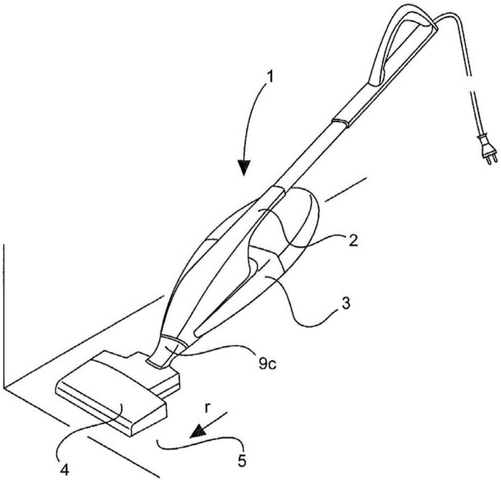
[0038] attached figure 1 A vacuum cleaner 1 is shown with a disposal tube 2 , a base housing 3 and a suction nozzle 4 formed as a detachable attachment, which is placed on a floor 5 . A dust collection chamber (not shown) is provided in the base shell 3, and a dust filter bag is provided in the dust collection chamber, and the dust and / or dust particles entrained from the floor 5 to be treated or to be cleaned pass through the dust filter bag through the suction flow. Gather in. Furthermore, a fluid-tight connection is formed between the suction nozzle 4 and the dust collection chamber.

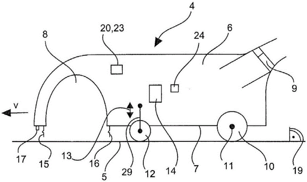
[0039] attached figure 2The suction nozzle 4 is shown schematically in side view. The suction nozzle 4 has a base body 6 made of plastic, the bottom surface 7 of which is flush with the floor 5 . On the front side of the suction nozzle 4 in the direction of travel r, a channel running transversely to the direction of travel r is formed in the base body 6 as a suction chamber 8 . Brushes...


PUM


Abstract

The present invention relates to a nozzle (4) of a cleaner (1) for caring floors (5). The bottom (7) of the nozzle (4) is provided with a matrix (3) with a supporting wheel (12) which is used for allowing the flow to turn and allow the nozzle (4) to connect with a connection join (9c), and the supporting wheel (12) is able to lift and sink with respect to the bottom (7). Therefore, the forming nozzle (4) is able to lift the supporting wheel (12) after the connection join (9c) is converted to a stop position, the force of the supporting wheel (12) is too large, and/or the electric power consumed by the air pump motor of the cleaner (1) and the control signals reduced according to a preset value are received.

Description

technical field [0001] The invention relates to a suction nozzle for a vacuum cleaner for floor care, wherein the suction nozzle has a base body with supporting wheels arranged on its underside, and a connecting joint for deflecting the suction flow and connecting the suction nozzle to the vacuum cleaner. The invention also relates to a vacuum cleaner for floor care and a battery-operated vacuum cleaner with an extractor motor and a suction nozzle for generating a suction flow. Furthermore, the invention relates to a method for retracting support wheels of a vacuum cleaner and of a suction nozzle of a battery-operated vacuum cleaner. Background technique [0002] Vacuum cleaners are known in the prior art and have a base housing in which an electrically driven suction motor is arranged for generating a suction flow. It is known in practice that suction nozzles as accessories, also referred to simply as suction nozzles or, depending on the purpose of use, as hard floor nozzl...

Claims


Application Information

Patent Timeline
Patent Type & Authority Applications(China)
IPC IPC(8): A47L9/02A47L9/00
CPCA47L9/009A47L9/0054A47L9/28A47L9/2831A47L9/2852
Inventor 德克·赫尔隆马蒂亚斯·许西格罗伯特·普拉赫特卡
Owner VORWERK & CO INTERHOLDING GMBH
Why Eureka
Try Eureka