Jaw direction adjustment mechanism of endoscope cutting stapler

A direction adjustment and stapler technology, which is applied in the field of medical devices, can solve problems such as flexibility constraints, large operating force, and inability to effectively prevent jaws from swinging back or blocking, and achieve the effect of easy and labor-saving adjustment mechanism

Active Publication Date: 2016-05-25
CHANGZHOU KANGDI MEDICAL STAPLER
View PDF10 Cites 4 Cited by
  • Summary
  • Abstract
  • Description
  • Claims
  • Application Information

AI Technical Summary

Problems solved by technology

Patent 1 uses two wave beads whose axes are parallel to the axis of the joint knob. The pressure spring inside it has small elasticity. Although the operation feels light, the disadvantage is that the jaws in the turning state will swing back when the thick tissue is fired, and the joint knob will jump gears. Unable to position and lock the jaws of the stapler, which is not reliable enough
Moreover, if simply increasing the elastic force of the pressure spring inside the ball, it will be a big risk that the welding strength of the upper and lower covers of the rotary head will be separated for a long time
Patent 2 uses a plurality of wave springs on the same axis as the joint knob to superimpose and press the upper and lower chainrings, and relies on the triangular tooth groove meshing. Although the greater the spring force, the less likely it is to prevent the jaws from swinging back, the disadvantage is that the triangular The meshing area of ​​the tooth groove is large, the friction resistance is large, and the required operating force is also large, and the force of the wave spring pressing the upper tooth plate is directly felt by the operator, so the greater the wave spring pressing force, the more laborious it is to operate the joint knob
In view of the fact that the hand feeling of the surgeon operating the instrument is biased and diffi

Method used


Image

  • Jaw direction adjustment mechanism of endoscope cutting stapler
  • Jaw direction adjustment mechanism of endoscope cutting stapler
  • Jaw direction adjustment mechanism of endoscope cutting stapler

Examples


Embodiment Construction

[0022] The present invention is described below in conjunction with accompanying drawing.

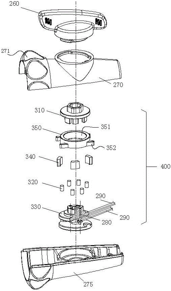
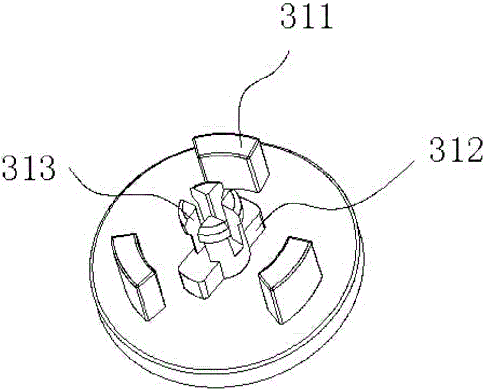
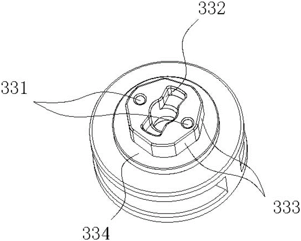
[0023] as attached Figure 1-7As shown, the jaw direction adjustment mechanism of a laparoscopic cutting stapler according to the present invention includes a joint knob 260, a rotating head and a two-way adjusting assembly 400. The two-way adjusting assembly 400 is rotatably arranged in the rotating head, and the rotating head Divided into an upper swivel head 270 and a lower swivel head 275; the two-way adjustment assembly 400 includes a main turntable 310, an outer ring 350, three elastic bodies 340, six rollers 320, an inner star wheel 330, and two pin shafts 280 and two joint push rods 290; the joint knob 260 is rotatably arranged on the upper rotary head 270, the top surface of the main turntable 310 cooperates with the joint knob 260 through a hexagonal boss structure, and the bottom surface is provided with a transmission pin 312, a card Pin 313 and three circularly distributed...


PUM


Abstract

The invention discloses a jaw direction adjustment mechanism of an endoscope cutting stapler. The jaw direction adjustment mechanism comprises a joint rotary knob, a rotating head and a bidirectional adjustment assembly. The bidirectional adjustment assembly is rotationally arranged in the rotating head and comprises a main rotating disc, an outer ring, a plurality of elastomers, a plurality of rollers, an inner planet gear, two pin shafts and two joint push rods. A transmission pin, clamping feet and pulling claws are arranged on the bottom face of the main rotating disc. A positioning column and a matched boss are arranged on the inner planet gear. The outer ring is located between the main rotating disc and the inner planet gear, the yoke face of an inner hole of the outer ring is matched with the positioning column, the pulling claws, the rollers and the elastomers are sequentially arranged between the yoke face of the inner hole of the outer ring and the matched boss at intervals, the rollers are always attached to the working face of the inner planet gear through the elastomers, and a bidirectional overrunning clutch locking structure is formed. The function of bidirectionally adjusting a jaw of the stapler through the bidirectional adjustment assembly is achieved, backswing of the jaw is effectively avoided, operation is easier and saves more labor, and an operator can feel changes of adjustment of the jaw in time.

Description

technical field [0001] The invention relates to a jaw direction adjustment mechanism of an endoscopic cutting stapler capable of bidirectional locking at multiple positions, and belongs to the technical field of medical instruments. Background technique [0002] The application number of the Chinese invention patent "Cutting Stapler Suitable for Minimally Invasive Surgery" is CN201310263622.9, and the following is briefly described as Patent 1, which discloses a surgical instrument. The rotating joint knob drives the joint base to rotate synchronously, and the 2 A pin shaft drives two joint push rods to slide back and forth, so that the two joint connecting plates inside the executive component drive the jaws to rotate and adjust around the hinge pins, and the top ball of the positioning bead is embedded in the joint seat for corresponding positioning under the action of the spring force. In the groove, the positioning beads block the joint seat by means of friction and do n...

Claims


Application Information

Patent Timeline
IPC IPC(8): A61B17/072
CPCA61B17/07207A61B2017/2927A61B17/072A61B2017/07221A61B2017/07285
Inventor 杨卫民
Owner CHANGZHOU KANGDI MEDICAL STAPLER
Why Eureka
Try Eureka