Remote control lifting function column

A technology of functional columns and fixed columns, which is applied in the direction of laboratory stools/tables, etc., can solve the problems of unfavorable movement of experimental personnel, unfavorable handling of experimental items, and occupation of ground space, so as to solve the problem of messy ground wiring and convenient and fast control , the effect of high efficiency

Active Publication Date: 2017-12-12
DOAP SCI & TECH DEV CO INC
View PDF6 Cites 0 Cited by
  • Summary
  • Abstract
  • Description
  • Claims
  • Application Information

AI Technical Summary

Problems solved by technology

[0002] There are many kinds of experimental equipment. For the convenience of the experiment, it is necessary to set up the experimental workbench. Due to the difference in the layout of the laboratory space, the experimental workbench is placed on the wall. In order to improve the utilization of space, it is also placed in the laboratory. In the middle position, the workbench placed in the middle position becomes the central workbench. At present, whether it is a side-mounted or a central workbench, due to the limitation of the placement position, the layout of the gas circuit, water circuit and circuit is mostly directly connected to the external equipment. Occupies a certain amount of ground space, resulting in uneven ground, which is not conducive to the handling of other experimental items, and is not conducive to the movement of experimenters

Method used


Image

  • Remote control lifting function column
  • Remote control lifting function column
  • Remote control lifting function column

Examples


Embodiment Construction

[0020] It should be noted that, in the case of no conflict, the embodiments of the present invention and the features in the embodiments can be combined with each other.

[0021] In describing the present invention, it should be understood that the terms "center", "longitudinal", "transverse", "upper", "lower", "front", "rear", "left", "right", The orientations or positional relationships indicated by "vertical", "horizontal", "top", "bottom", "inner", "outer", etc. are based on the orientation or positional relationships shown in the drawings, and are only for the convenience of describing the present invention Creation and simplification of description, rather than indicating or implying that the device or element referred to must have a specific orientation, be constructed and operate in a specific orientation, and therefore should not be construed as limiting the invention. In addition, the terms "first", "second", etc. are used for descriptive purposes only, and should no...


PUM


Abstract

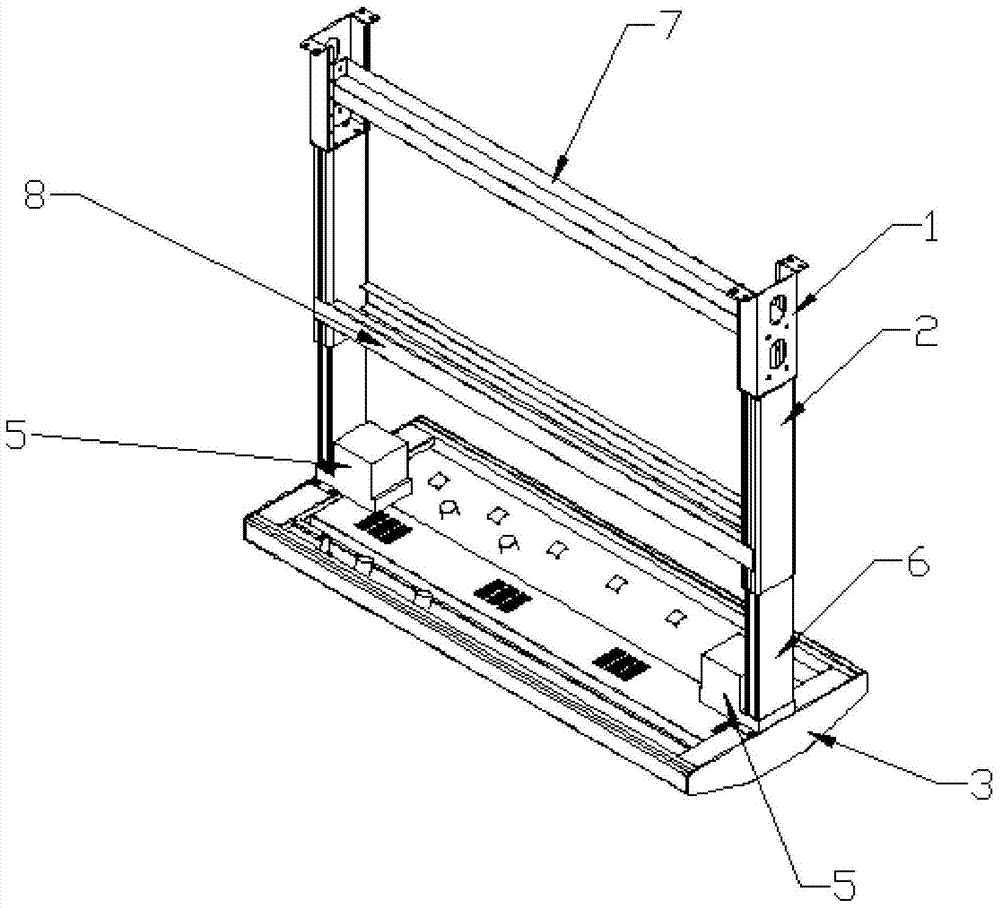
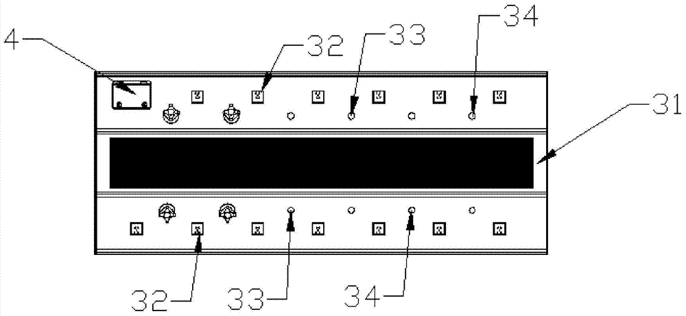
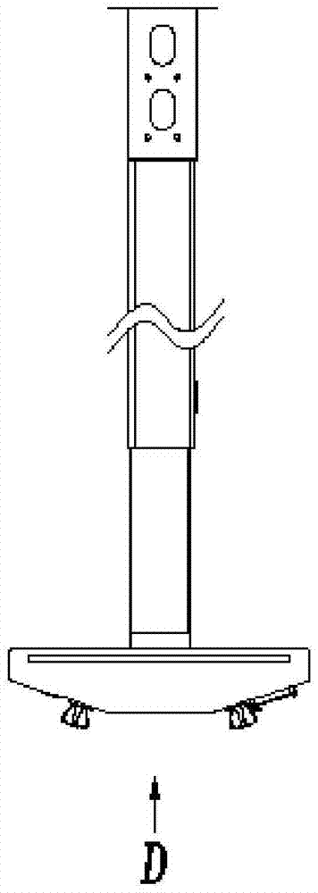
The invention provides a remotely-controllable liftable functional column. The remotely-controllable liftable functional column comprises a fixed frame, a fixed column, a movable column, a synchronous motor, an electric control panel and an integrated panel, wherein the upper end of the fixed frame is fixed at the corresponding top above an experiment table; the fixed column is perpendicular to a horizontal plane, and one of the fixed column and the lower end of the fixed frame are fixedly connected; the movable column are arranged vertically; the synchronous motor is arranged at one end, away from the fixed column, of the movable column; the synchronous motor can realize a sliding connection of the fixed column and the movable column through a nut and screw mechanism; the integrated panel is arranged horizontally, and is fixedly connected with the lower end surface of the movable column; the electric control panel is arranged on the lower end surface of the integrated panel and can control operation of the synchronous motor; the electric control panel is controlled by a wireless signal or an infrared signal. The remotely-controllable liftable functional column can realize wiring of three pipelines, namely water, electricity and gas from the interior of the experiment table, the wiring is simpler and more integrated, and the problems of messy wiring on the ground and potential safety hazards are solved; in addition, the remotely-controllable liftable functional column is capable of being controlled by a mobilephone and the like having an infrared device to finish lifting of the integrated panel; the remotely-controllable liftable functional column provided by the invention is more convenient to operate, and the working efficiency is promoted.

Description

technical field [0001] The invention belongs to the field of experimental equipment, and in particular relates to a remote control liftable functional column. Background technique [0002] There are many kinds of experimental equipment. For the convenience of the experiment, it is necessary to set up the experimental workbench. Due to the difference in the layout of the laboratory space, the experimental workbench is placed on the wall. In order to improve the utilization of space, it is also placed in the laboratory. In the middle position, the workbench placed in the middle position becomes the central workbench. At present, whether it is a side-mounted or a central workbench, due to the limitation of the placement position, the layout of the gas circuit, water circuit and circuit is mostly directly connected to the external equipment. Occupies a certain amount of ground space, resulting in uneven ground, which is not conducive to the handling of other experimental items, ...

Claims


Application Information

Patent Timeline
Patent Type & Authority Patents(China)
IPC IPC(8): B01L9/02
CPCB01L9/02
Inventor 靳喆滕杰
Owner DOAP SCI & TECH DEV CO INC
Why Eureka
Try Eureka